Combinational Logic
CS-A1120 Programming 2
Lukas Ahrenberg
Department of Computer Science
Aalto University
(Based on material by Petteri Kaski and Tommi Junttila)
Boolean operators recalled
Last week we got familiar with the following operators:
AND, OR, NOT, and XOR (in Scala: &, |, !, ^).
Below are truth tables (given input a, b) for these operators - but, I have masked them by 🦍 🐳 🦑 🦆
Which one is which?
| a | b | a 🦍 b |
|---|---|---|
| 0 | 0 | 0 |
| 0 | 1 | 1 |
| 1 | 0 | 1 |
| 1 | 1 | 1 |
| a | 🐳a |
|---|---|
| 0 | 1 |
| 1 | 0 |
| a | b | a 🦑 b |
|---|---|---|
| 0 | 0 | 0 |
| 0 | 1 | 1 |
| 1 | 0 | 1 |
| 1 | 1 | 0 |
| a | b | a 🦆 b |
|---|---|---|
| 0 | 0 | 0 |
| 0 | 1 | 0 |
| 1 | 0 | 0 |
| 1 | 1 | 1 |
After this round, you
- can identify basic logic gates, and read and draw simple circuit diagrams
- can combine gates and buses to build logic functions
- are aware of how Scala structures can be used to simulate logic expressions
Goal for today
A "machine" that adds up numbers
Previously
- A bit is used to represent two states (0/1), (True/False), …
- Sequences of bits can be used to represent data (e.g. a number)
- Boolean operations (AND, OR, NOT,…) is used to transform bits & data
What are the principles by which computers operate?
How to build machines that compute with bits?
- Computing:
- "Top-down" : Turing machines
- "Bottom-up" : Gates and circuits
Construction kit for a computer
- Logic gates NOT, AND, OR
- Some 'wire' to connect them with
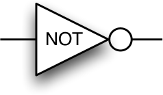
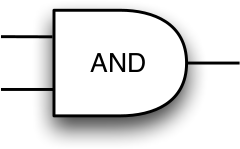
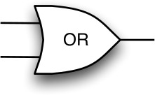

We call these gates
Gates as Boolean operations
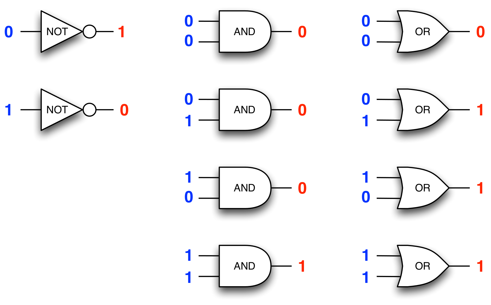
(The output (value) of a gate is determined by the inputs )
Logic gates - physical implementations
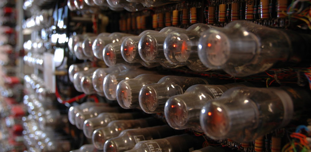
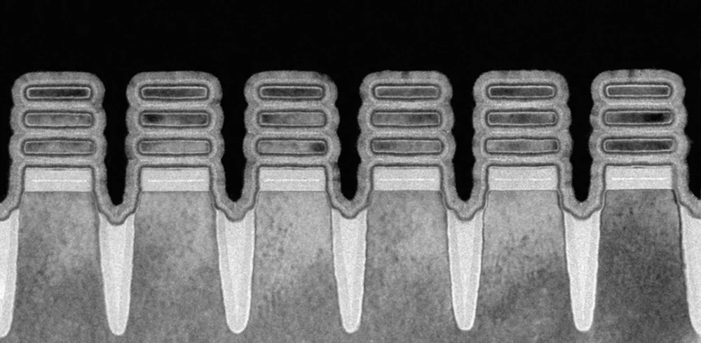
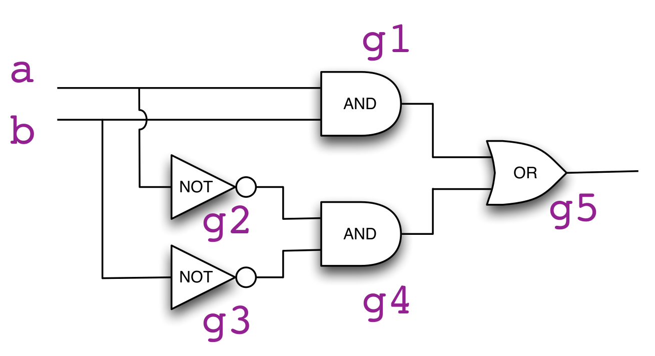
What kind of machines can be built by combining logic gates?
Circuits
- A combination of gates is called a circuit
- A circuit has inputs and output
- Compare this 'box' to a function…
out
?
?
?
?
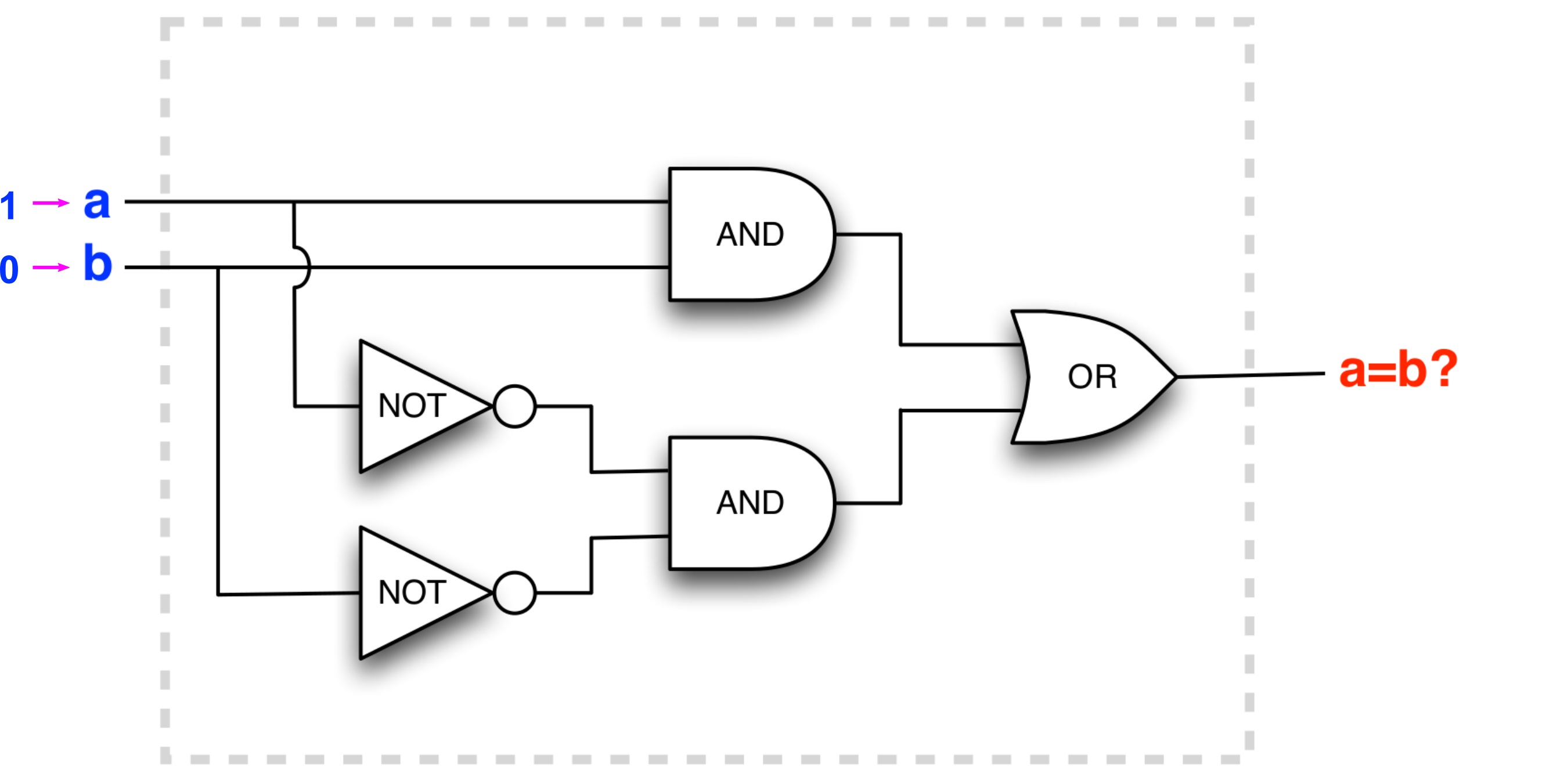
0
The circuit outputs changes with input !
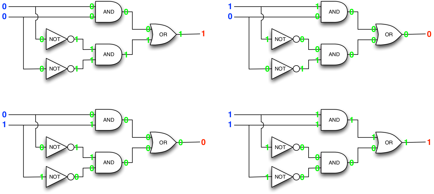
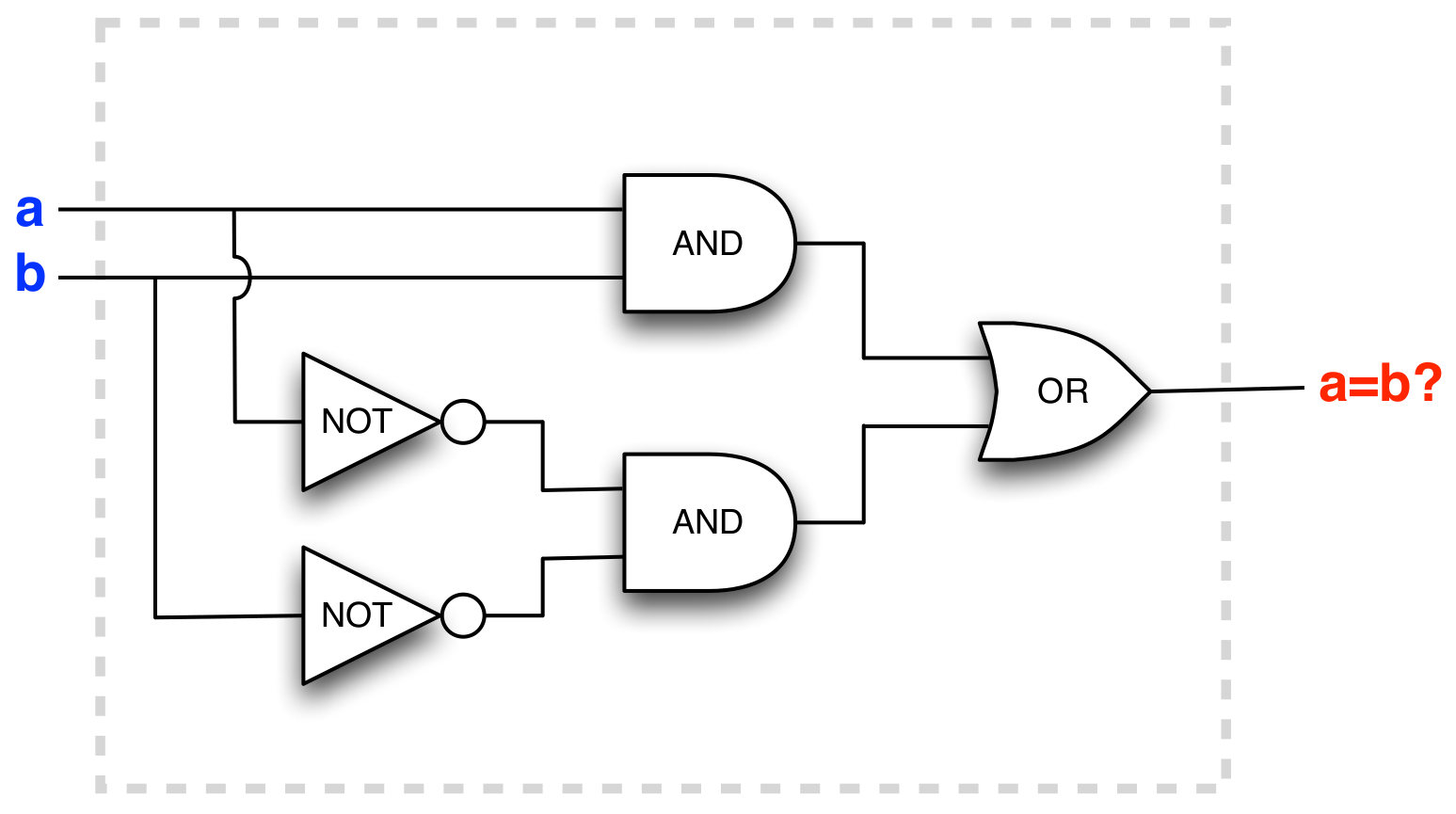
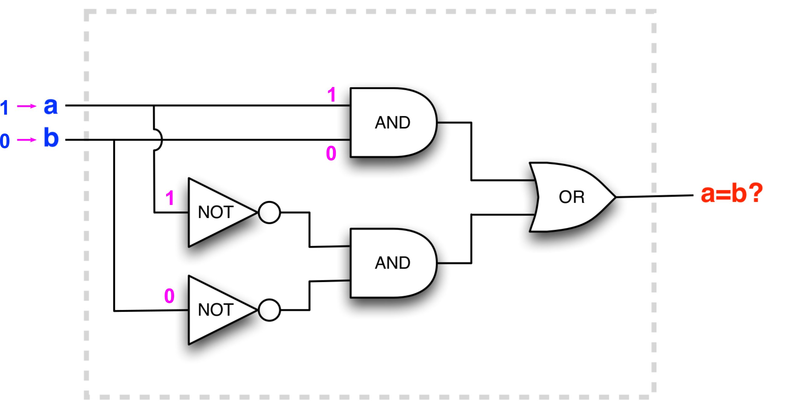
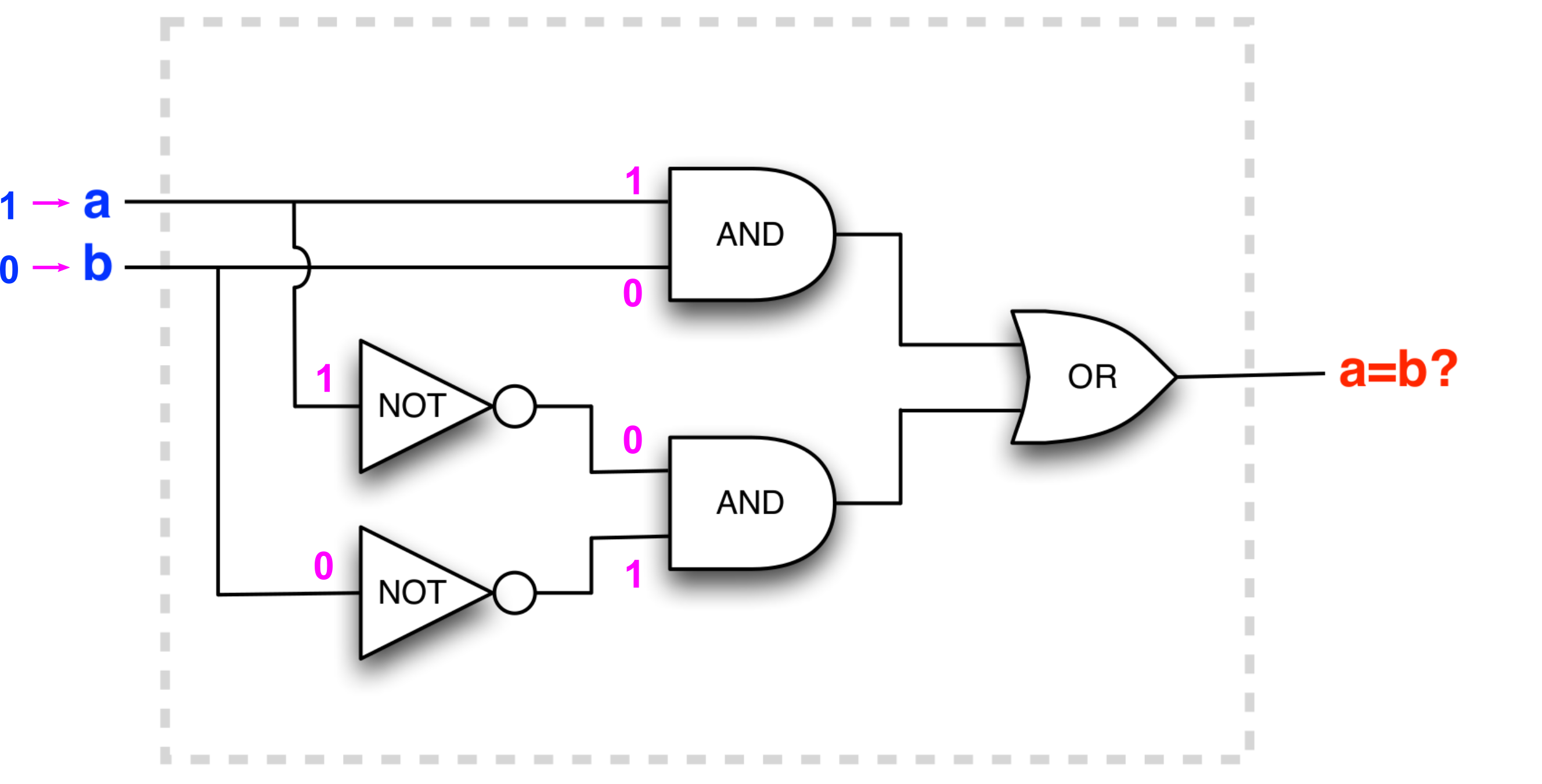
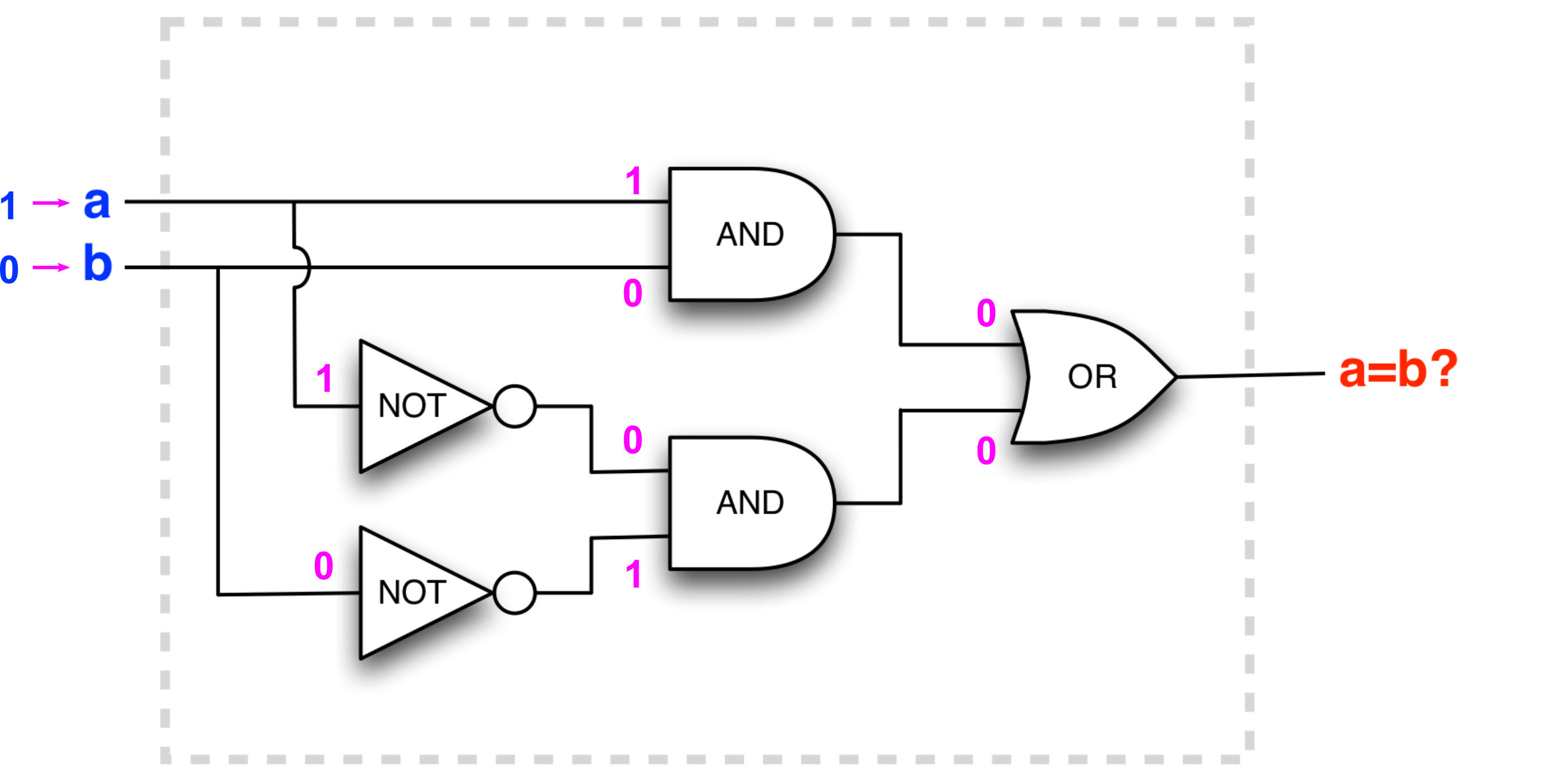
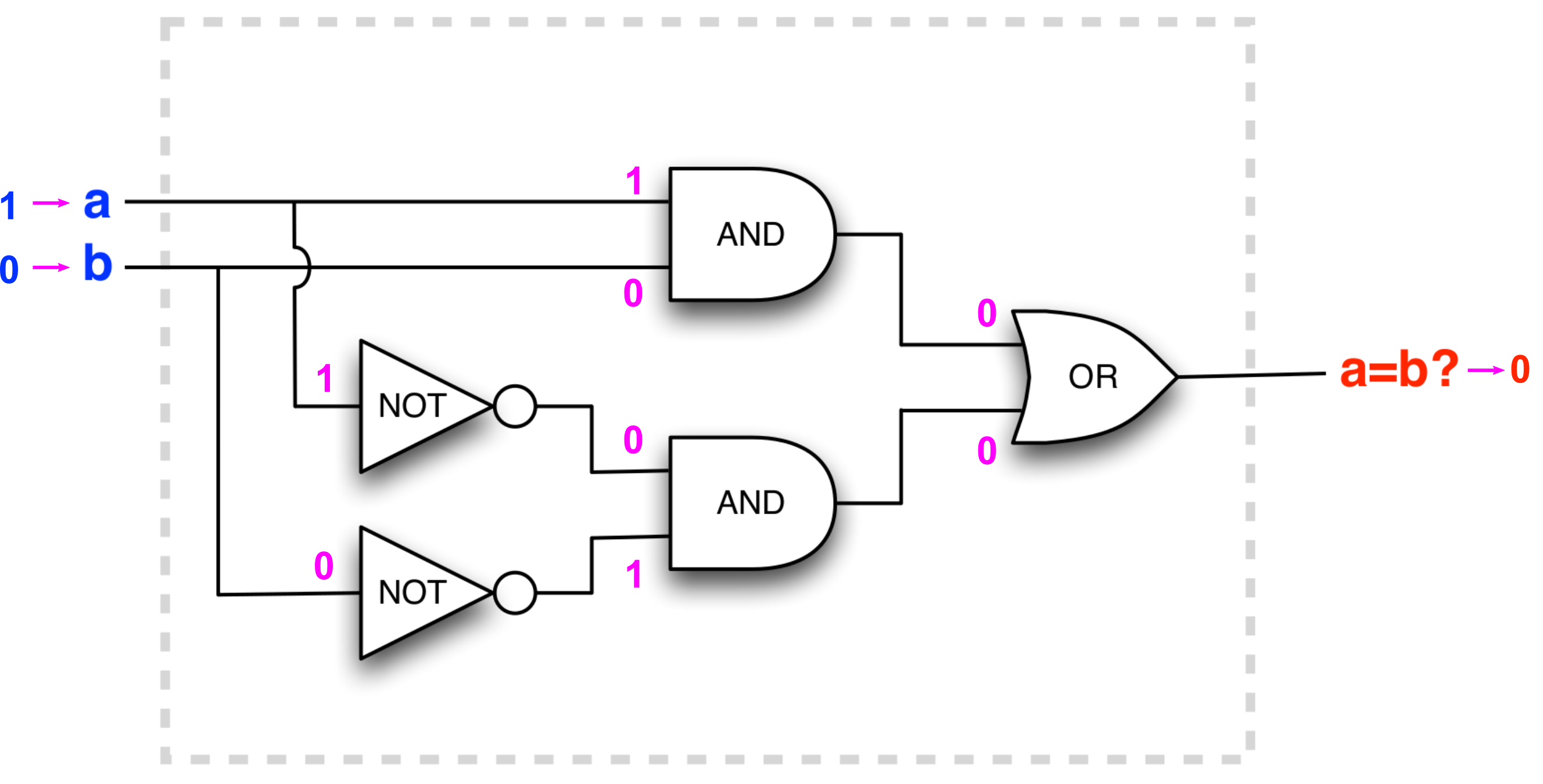
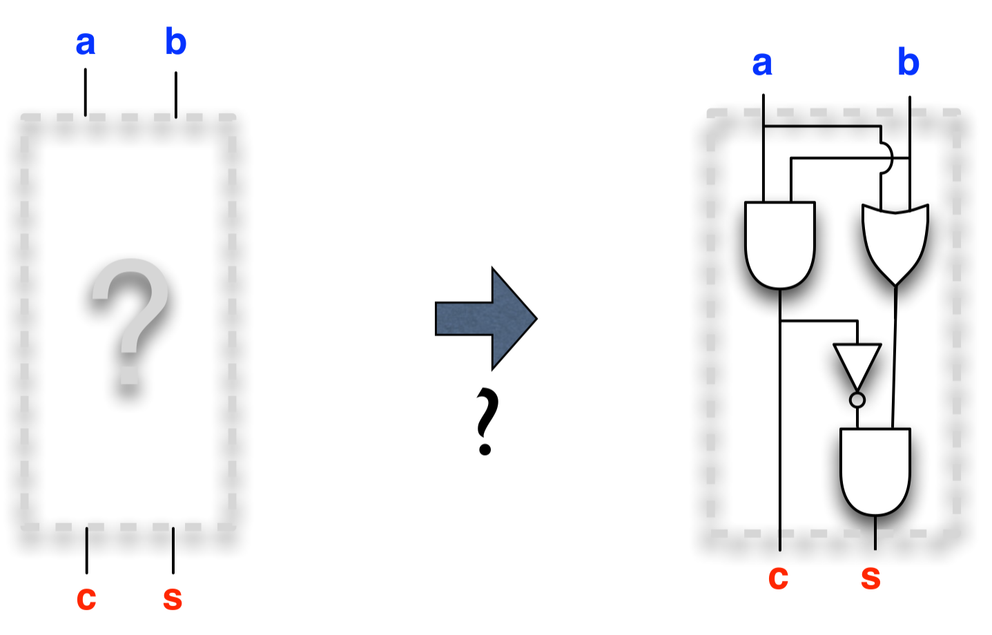
Question: what does the circuit compute?
out
- a) What Boolean expression does the circuit correspond to?
- b) What 'function' does it compute, in your own words (once sentence)?
(a & b) | (!a & !b)
| a | b | (a & b) | (!a & !b) |
|---|---|---|
| 0 | 0 | 1 |
| 0 | 1 | 0 |
| 1 | 0 | 0 |
| 1 | 1 | 1 |
truth table
Round 1 recalled – classes to represent expressions
abstract class Value:
  def read: Int
end Value

class VariableValue(c: Int) extends Value:
  protected var _myVal = c
  def write(v: Int) =
    _myVal = v
  def read = _myVal
end VariableValue

class SumValue(v1: Value, v2: Value) extends Value:
  def read = v1.read + v2.read
end SumValue
val v1 = VariableValue(10)
val v2 = VariableValue(20)
val s = SumValue(v1,v2)

println(f"The sum is now ${s.read}")

v1.write(0)

println(f"The sum is now ${s.read}")
The sum is now 30
The sum is now 20
val x = VariableValue(10)
val y = VariableValue(20)
val z = VariableValue(30)

val sum1 = SumValue(SumValue(x,y),z)
val sum2 = VariableValue((x.read+y.read) +z.read)

print(f"A:${sum1.read},")
print(f"B:${sum2.read},")

x.write(100)

print(f"C:${sum1.read},")
print(f"D:${sum2.read},")

Emulating circuits in Scala
Let's write a Scala programmer's construction kit for a circuit (and, later, a computer)!
We will need to represent:
What if we used objects…
to represent gates
as well as inputs.
And their inputs were 'previous' gates or input elements
Then that should take care of the wiring.
And the 'output' is the value of the last gate object in the chain.
Making a Scala package: tinylog
package tinylog
Let's use common abstract class for logic gates and inputs
abstract class Gate():
   def value: Boolean // implemented by the extending classes
end Gate
Implementing the logic gates
class NotGate(in: Gate) extends Gate():
  def value = !in.value
end NotGate

class OrGate(in1: Gate, in2: Gate) extends Gate():
  def value = in1.value || in2.value
end OrGate

class AndGate(in1: Gate, in2: Gate) extends Gate():
  def value = in1.value && in2.value
end AndGate
And inputs
class InputElement() extends Gate():
  var v = false                     // default value is false
  def set(s: Boolean) = { v = s }
  def value = v
end InputElement
(Compare to the polynomial expression exercise in round 1.)
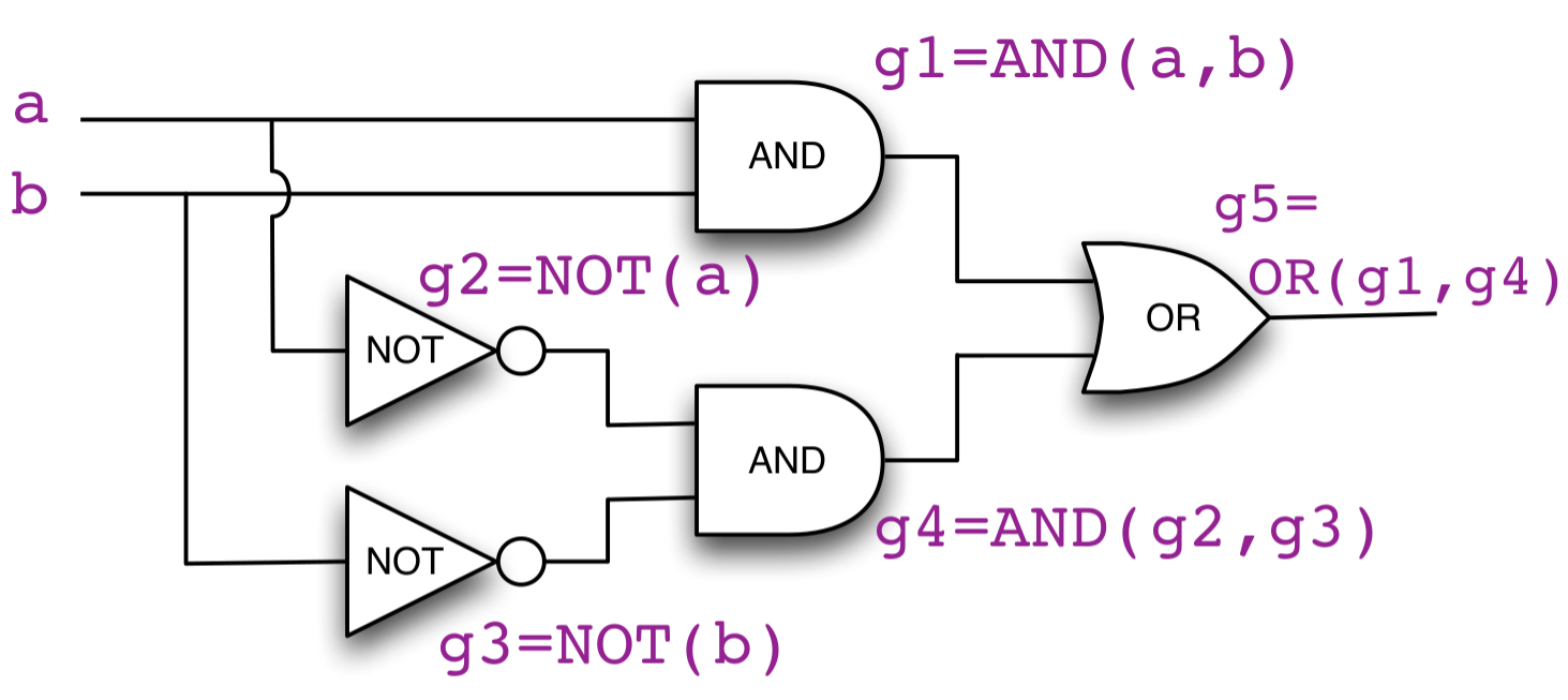
Building the example circuit in Scala
import tinylog.*
// Build a simple circuit
val a = InputElement()
val b = InputElement()
val g1 = AndGate(a,b)
val g2 = NotGate(a)
val g3 = NotGate(b)
val g4 = AndGate(g2,g3)
val g5 = OrGate(g1,g4)
Then we can test it:
scala> a.set(true)
scala> b.set(false)
scala> g5.value
val res1: Boolean = false

scala> a.set(false)
scala> b.set(false)
scala> g5.value
val res2: Boolean = true
Note how the circuit works as a function - when we change the input it 'recalculates' the output.
Improving syntax by specifying operators
- Scala allows us to define our own operators (such as
&&||+-/…) for classes - In this case it would make sense to have
&&,||,!act as short-cuts for AND, OR, and NOT gates
We extend our abstract Gate class somewhat:
class Gate():
  /** Boolean value of the Gate.*/
  def value: Boolean

  /** Operator definition for NotGate of this Gate.*/
  def unary_! = new NotGate(this)
  /** Operator definition for AndGate of this Gate and that Gate.*/
  def &&(that: Gate): Gate = new AndGate(this, that)
  /** Operator definition for OrGate of this Gate and that Gate.*/
  def ||(that: Gate): Gate = new OrGate(this, that)
end Gate
Using the operators
import tinylog.*
// Build a simple circuit
val a = InputElement()
val b = InputElement()
val g1 = a && b
val g2 = !a
val g3 = !b
val g4 = g2 && g3
val g5 = g1 || g4
import tinylog.*
// Build a simple circuit
val a = InputElement()
val b = InputElement()
val g5 = (a && b) || (!a && !b)
Scala creates the objects implicitly. Makes it easy to build large circuits.
Fine, but what about a machine that adds up numbers?
Let's start with a machine that adds up two single bit numbers
Adding up two single-bit numbers
\(0 + 0 = 0\)
\(0 + 1 = 1\)
\(1 + 0 = 1\)
\(1 + 1 = 10\)
Remember school: when the sum cannot 'fit' in a position we carry to the next.
\(0 + 0 = 00\)
\(0 + 1 = 01\)
\(1 + 0 = 01\)
\(1 + 1 = 10\)
Know the input/output – problem: need to find circuit (expression)
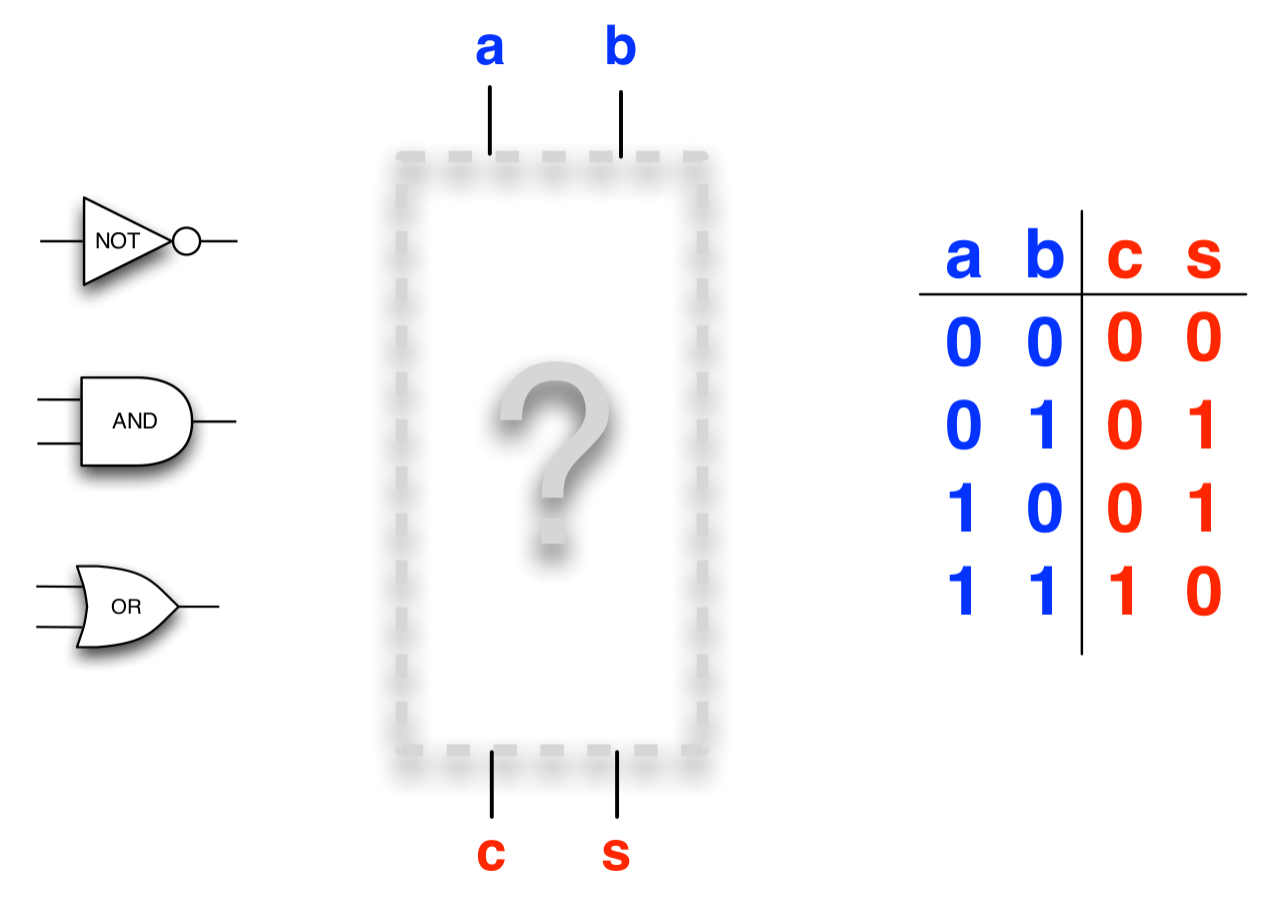
Which circuit performs one-bit addition?

Synthesis ?
Synthesis from truth table(s)
- In every row with output 1 write an AND operation which is true exactly when the inputs have the values of that row
- Combine these expressions to one long OR expression
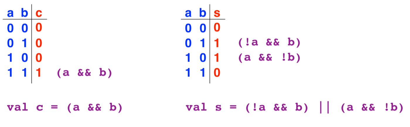
(Assuming the inputs (a, b) are tinylog Gate, then Scala will automatically create the circuit with these expressions!)
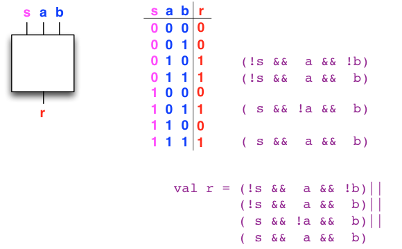
Synthesis example: selector (multiplexer)
- Assume we want to switch between two bits
aandb, using a selector bits:- If the selector,
s, is \(0\) we want the output,r, to have the same value asa, and if it is \(1\) the output should have the same value asb
- If the selector,
So, are we done? Synthesise the circuit to add 2 n-bit numbers!
A general procedure: Set up the truth table → build the formula We could, in principle, list all possible combination of inputs and outputs for the sum… any problems?
- … How large are these circuits actually?
- What if we build a machine to add two 64 bit integers?
- \(2 \times 64 = 128\) inputs
- Meaning that the truth table has \(2^{128} = 340282366920938463463374607431768211456\) rows
- Ouch, we need to be smarter
Building more complicated circuits smarter
- Gates hold only one bit each
- In order to represent data we need multiple bits
- Work with sequences of gates as an abstraction, and call it a bus
- Carries a word of multiple bits instead of wires with a single bit
- Better understanding of the specific task at hand could give insights in a better circuit design, using modular principles
Implementation of a Bus class in tinylog
- A
Busrepresents multiple bits (gates), so let's make it extend the Scala traitSeq- Meaning that
Busis a custom Scala collection forGateobjects
- Meaning that
- We'll also give it both bus-level operators for AND, OR, NOT (
&,|,~)- Recall the word-operations last round
You can read more about how Bus is constructed in the course notes, and find the source of Bus.scala in the tinylog sub-project of this round's exercises.
Because Bus is a Seq we have access to the usual methods for collections, such as map and fold.
Example: building a bus selector
aa if s is 0 and bb if s is 1:
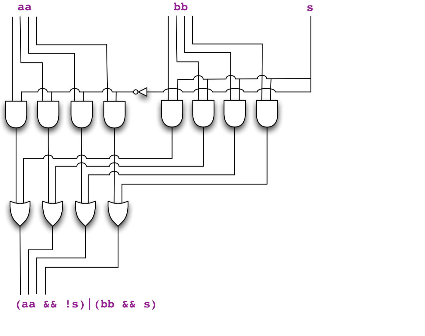
scala> import tinylog.*_
scala> val aa = Bus(Gate.False, Gate.True, Gate.True, Gate.True)

scala> val bb = Bus(Gate.True, Gate.False, Gate.False, Gate.False)

scala> val s = Gate.input() // Use an input gate so we can select

scala> val cc = (aa && !s) | (bb && s) // Construct the circuit

scala> cc.values // By default s is false, so we will select aa
val res0: Seq[Boolean] = List(false, true, true, true)

scala> s.set(true) // But, by setting s to true...

scala> cc.values // The circuit output has changed to bb
val res2: Seq[Boolean] = List(true, false, false, false)
Toggler to display an UI:
scala> val t = Toggler() // Create toggler UI

scala> t.watch("aa",aa) // Display bus aa

scala> t.watch("bb",bb) // Display bus bb

scala> t.watch("s",s) // Display selector bit

scala> t.watch("cc", cc) // Display output bus cc

scala> t.go() // And start
Video of similar demo is here
Example: Palindrome
Bus contains a bit-palindrome.
- First, it can be a good idea to sketch a 'circuit' describing what we want to do.
- "Check if first gate is equal to last, check if second gate is equal to second last…"
- If all these checks are true then we have a palindrome
- Is there some operation we have not expressed using Boolean logic?
- Yes, the equality check
=? - But we know how!
(a && b) || (!a && !b)
- Yes, the equality check
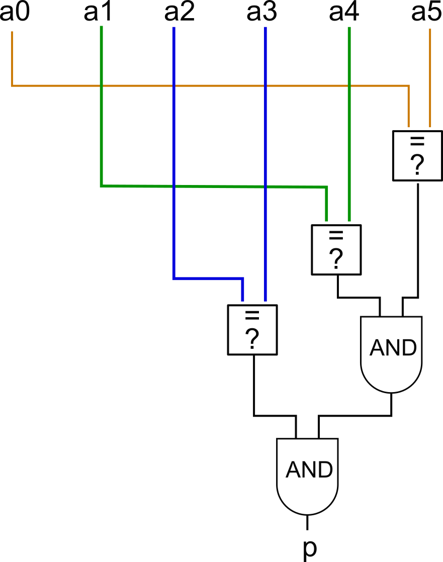
10101 is a palindrome; 11001 is not.) Example: Palindrome
// Helper function - output gate is true when input
// gates are equal
def gatesEqCircuit(a : Gate, b : Gate) : Gate =
  (a && b) || (!a && !b)

// Output gate is true when input bus is a palindrome
def isPalindromeCircuit(aa: Bus) : Gate =
  val len = aa.length
  // Create an array of size len/2 to hold the eq gates
  val eqc = new Array[Gate](len/2)
  for i <- 0 until len/2 do
    eqc(i) = gatesEqCircuit(aa(i), aa(len-1-i))
  end for
  // Now we can just reduce it with AND to form the
  // final gate
  eqc.reduce(_ && _)
end isPalindromeCircuit
val aa = Bus.inputs(7)
val p = isPalindromeCircuit(aa)
val t = Toggler()
t.watch("Input",aa)
t.watch("Palindrome?",p)
t.go()
NOTE: At no point does the code need to check the value of a gate when we build the circuit!
Demo video
What does the circuit returned by f do?
import tinylog.*

def e(a:Gate, b:Gate) = (a && b) || (!a && !b)

def f(aa:Bus, bb:Bus) =
  require(aa.length == bb.length)
  val x = aa.zip(bb).map((a,b) => e(a,b))
  x.reduce(_ && _)
end f
Fine, but…
What about a 64 bit machine that adds up two 64 bit numbers?
What exactly do we do when adding up two integers?
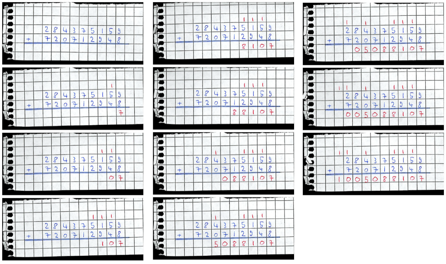
Back to School in base 10
Back to School in base 2
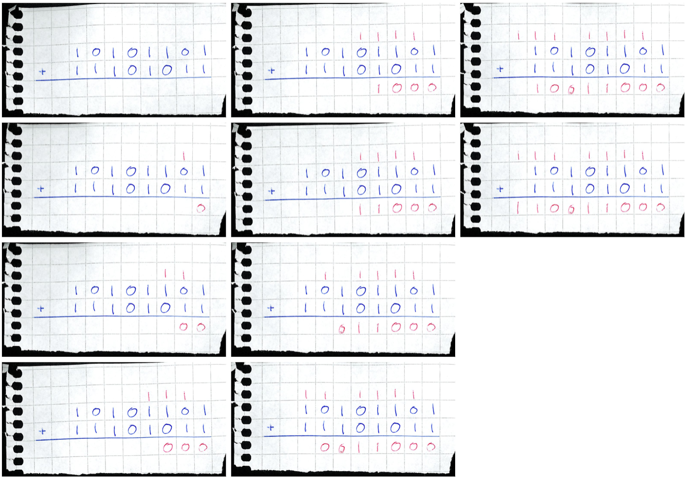
Addition is easy in binary!
Build a circuit that follows the procedure, one significant bit at a time.
- Every significant number is determined by adding up three numbers
- In binary, each are either
0or1.
- In binary, each are either
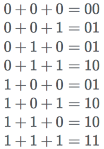
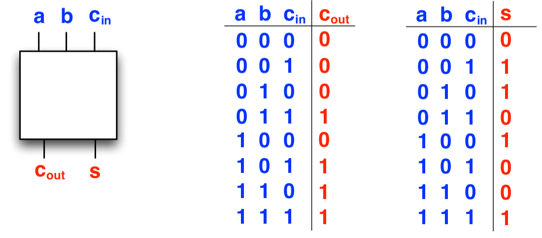
The Full adder
Call this circuit a Full adder
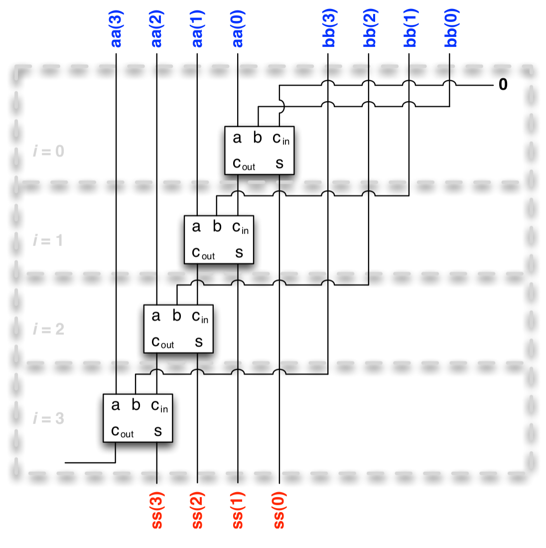
The Ripple-carry adder
- Connect the Full adder module one significant bit (starting with least significant) at a time
- Called a Ripple-carry adder because the carry bits spread out like ripples on a surface of water
Implementation:
  def buildFullAdder(a: Gate, b: Gate, c_in: Gate): (Gate, Gate) =
    val c_out = (!a && b && c_in) || (a && !b && c_in) || // ...
      (a && b && !c_in) || (a && b && c_in)
    val s = (!a && !b && c_in) || (!a && b && !c_in) || // ...
      (a && !b && !c_in) || (a && b && c_in)
    (c_out, s)
  end buildFullAdder

  def buildRCAdder(bus1: Bus, bus2: Bus) =
    require(bus1.length == bus2.length,
      "Can only add buses of same length")
    var carry_in: Gate = Gate.False // no initial carry
    val ss = new Array[Gate](bus1.length)
    for i <- 0 until bus1.length do
      val (carry_out, sum) = buildFullAdder(bus1(i), bus2(i),
        carry_in)
      carry_in = carry_out // carry from bit i propagates
      ss(i) = sum
    end for
    new Bus(ss.toIndexedSeq)
  end buildRCAdder
Example: 4 bit addition machine
Demo video
Gotcha when interpreting a Bus as a data word
Sequences are usually though of as indexed 'from left to right', but (binary) numbers are indexed (least significant digit) 'from right to left'.
For example, this constant three gate bus:
val aa = Bus(Gate.True, Gate.True, Gate.False)
represent the binary string 011.
Common pitfall when debugging exercises for example.
Exercises
- Circuit quiz
- Complete the truth table
- Tinlylog quiz
- Understand how to test gate values
- Gate expressions
- Two basic operations with
Gate
- Two basic operations with
- Operations on Circuits
- Different operations using circuits
- Note that count true bits cannot be implemented as in round 2
- Video explaining the unsigned less table if needed
- Bus writer
- Build a circuit that selects a bus and writes data to it
- (Challenge problem: Shallow operations)
- Drawing the circuit helps to figure out what to do
- These exercises are all about building circuits from
GateandBususing boolean operations - The values of
Gate(andBus) are not known when the circuit is constructed!- If you ever find yourself wanting to check the value of a
GateorBuswhen you build the circuit, code is probably wrong - Instead use the Boolean operators for
GateandBus- these are re-evaluated every time the input changes
- If you ever find yourself wanting to check the value of a
- The circuits and bus write exercises come with
*Play.scalamain programs- Skeleton code using
Triggerfor you to edit and play around with
- Skeleton code using