Sequential Logic
CS-A1120 Programming 2
Lukas Ahrenberg
Department of Computer Science
Aalto University
(Based on material by Petteri Kaski and Tommi Junttila)
Prefixing messages (don't do it like this)
- Assume we want a function
prefixPrintlnthat prints a string but inserts a line number and a user-configurable prefix first. - For example with the prefix set to "A>" and line numbers starting at 1, calling
prefixPrintln("Hello")should print[1]A>Hello, and if we made the same call again in the same session, we would expect[2]A>Hello.
// These var:s exist in the global scope
// [for the sake of demo, in general a bad idea]
var prefix = "A>"
var lines = 0
// println on the format [<lines>]<prefix><s>
def prefixPrintln(s: String) =
  lines +=1
  println(s"[$lines]$prefix$s")
scala> prefixPrintln("Hello")
[1]A>Hello

scala> prefix = "B>"
prefix: String = B>

scala> prefixPrintln("World")
[2]B>World
var's declared in the global scope- Note:
- Updating
prefixchanges how the function behaves - Line number is update every time
lines
- Updating
- Global
varis a bad idea
After this round, you
- know the limits of combinational logic
- can exemplify how the inclusion of feedback creates sequential logic
- have thought about the concept of programmability
- can explain the principle of state
- can build simple computing devices with evolving state using the course's minilog package
- have an overview of how a computer's data path is constructed
- can account for how computer memory works
Previously on Programming 2: we can build a machine that compute with bits
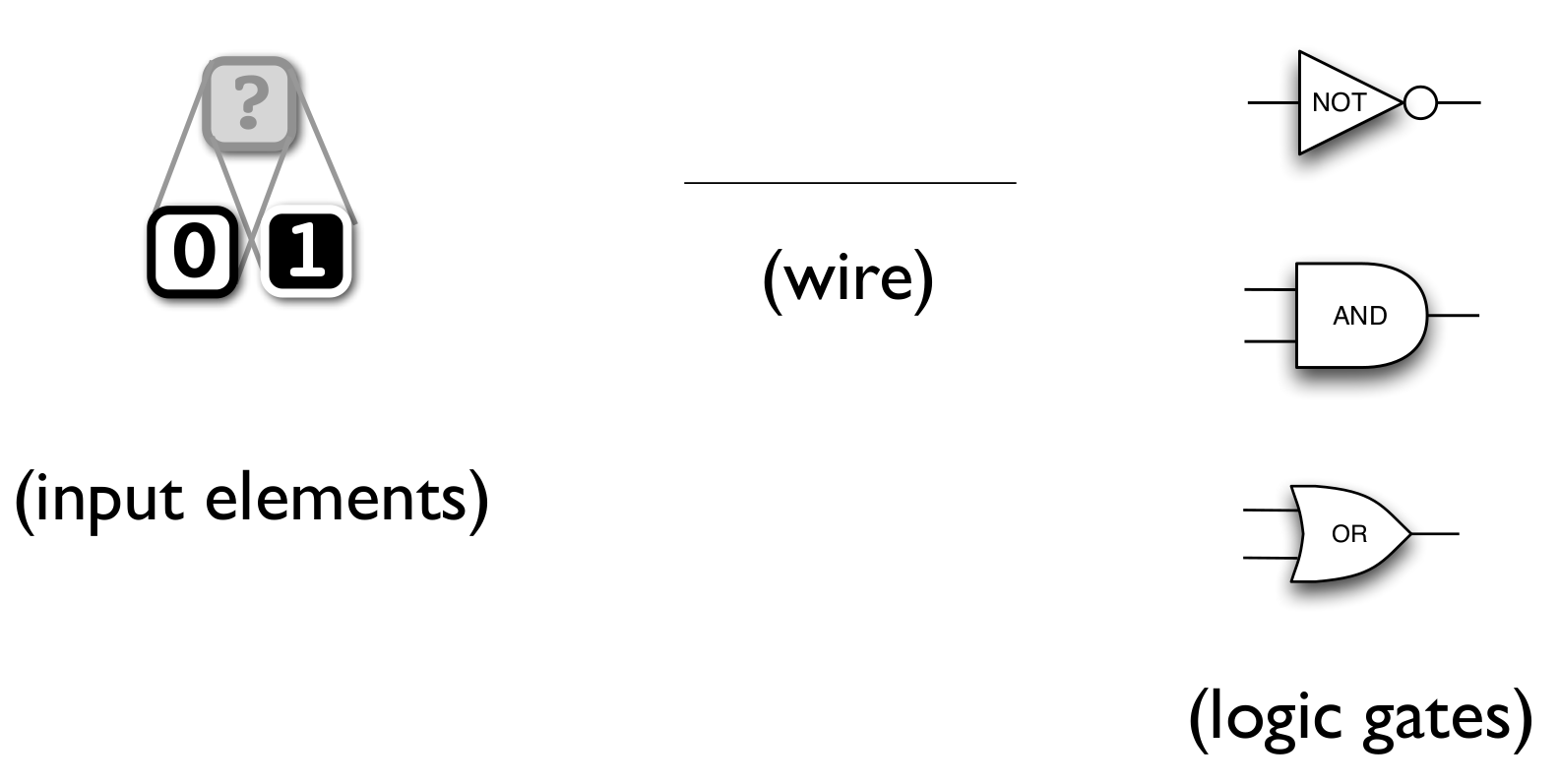
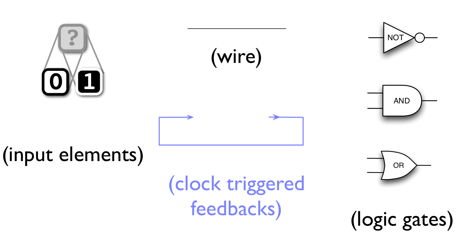
Using the building blocks of combinational logic:
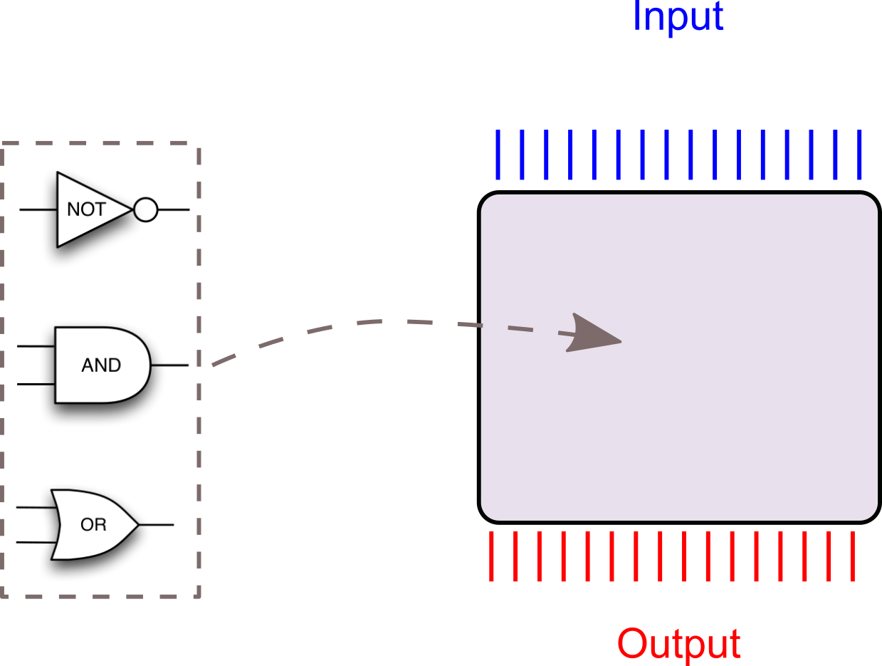
Is this enough to build a computer that can be programmed?
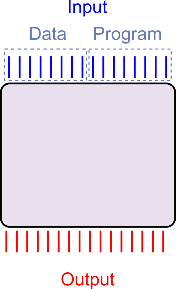
How do we build a programmable machine?
What does programmable entail?
https://presemo.aalto.fi/prog2/
Is combinational logic sufficient to build a programmable computer?
No (Intuitively)

What about a length \(m\) list of \(n\)-bit numbers?
So what about more general expressions?
Consider: combinational logic Adder/Subtracter
\(a \pm b\)
\(a + b\), if \(p = 0\)
\(a - b\), if \(p = 1\)
Could be built using one adder circuit, one subtracter circuit, and one multiplexer from last week.
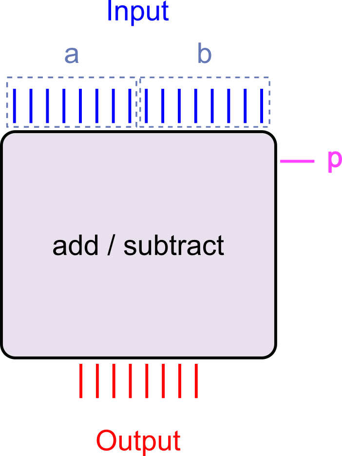
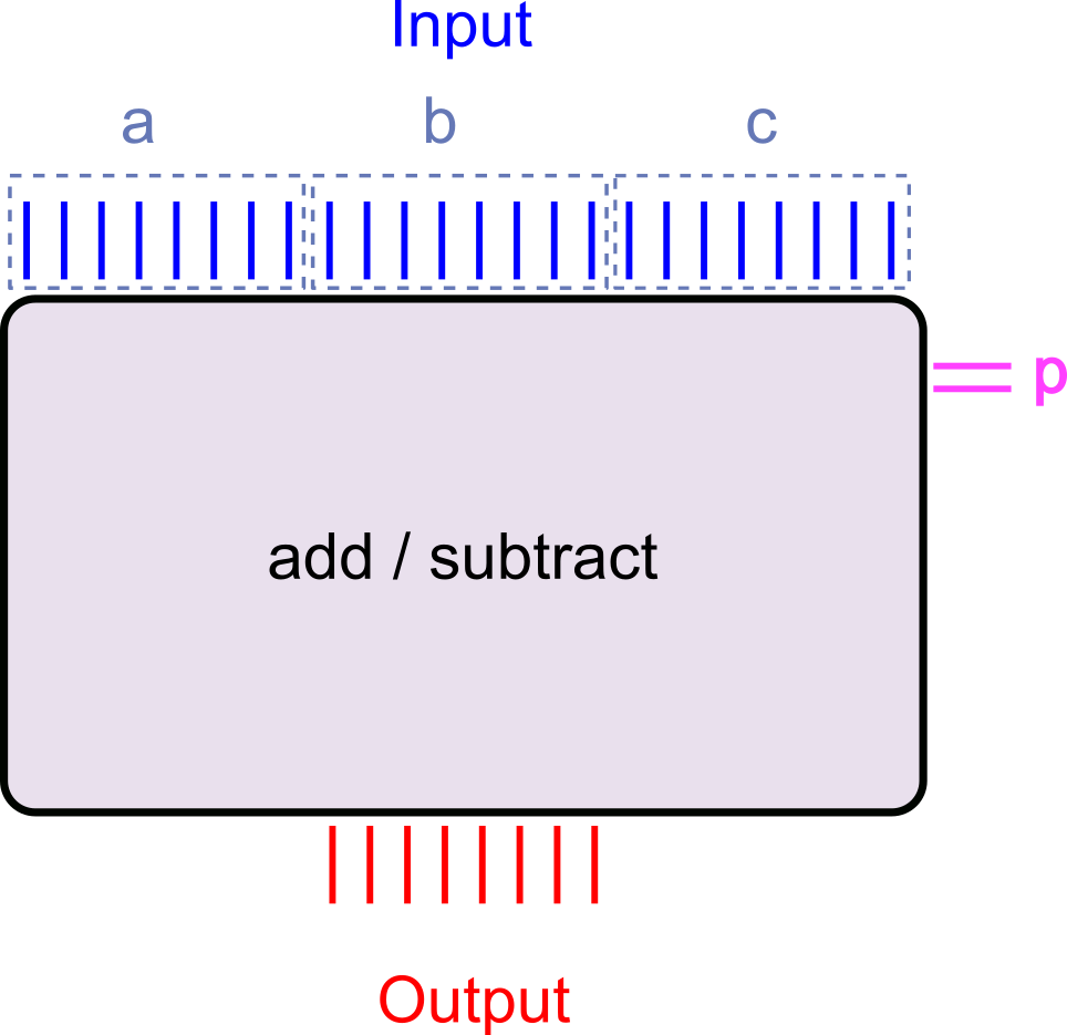
Three input words and two 'program' bits selecting the operation
\(\left(a\pm b\right) \pm c\)
\(\left(a + b\right) + c\), if \(p = 00\)
\(\left(a + b\right) - c\), if \(p = 01\)
\(\left(a - b\right) + c\), if \(p = 10\)
\(\left(a - b\right) - c\), if \(p = 11\)
Can still be built, but must implement each and every possible program path!
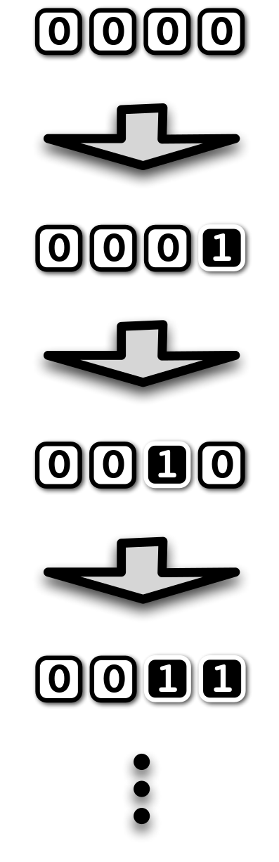
What is the 'smallest' machine that cannot be built using combinational logic?
- What about a machine that increases a counter by 1 every time we 'press a button'?
- Requires the machine to 'remember' the previous number
- Its current state
- But what is the 'button'?
- And what is the principle by which it operates?
Feedback
Feedback from outputs to inputs every time a 'button' is pressed
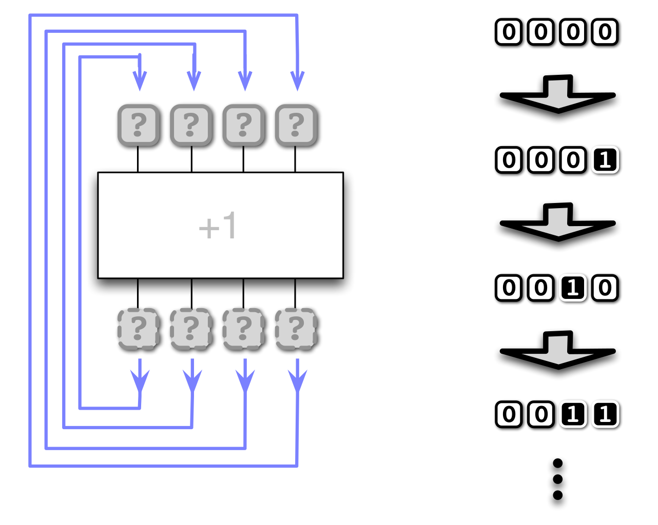
The clock
- The 'button press' is automated by including a clock in the circuit
- Every time the clock 'ticks' the feedback triggered
- Output values are read back to input causing the circuit to re-evaluate
- The clock drives the circuit state to be updated
- The faster the clock, the more updates (computations) per second
- Modern personal computers today have clock frequencies in the GHz range
The building blocks of Sequential Logic
Feedback quiz 1
What are the new values (left to right) in this four gate bus after triggering feedback once?
(Violet arrows indicate feedback.)


Feedback quiz 2
What are the new values (left to right) in this four gate bus after triggering feedback once?
(Violet arrows indicate feedback.)

Feedback quiz 3
What are the new values (left to right) in this four gate bus after triggering feedback once?
(Violet arrows indicate feedback.)

Is this enough to build a programmable computer?
We will need to engineer a few things to make it practical, but in principle Sequential logic is enough!
Why?
- Feedback allows the circuit to keep a state ('remember')
- Logic allows the circuit to evolve the state
- Functionality is configured not merely switched
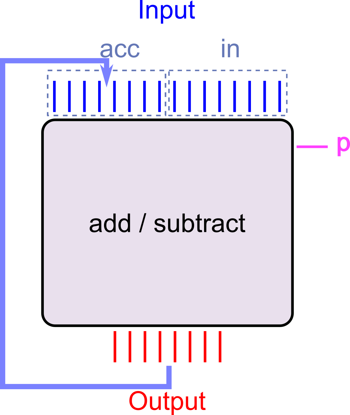
Hand waving - Sequential logic Adder-Subtracter
- Set
accto \(x_1\),into \(x_2\), andpto the operator, say \(0\) for \(+\), \(1\) for \(-\) - Clock circuit →
accis now the result of the addition / subtraction of the first two numbers - Set
into \(x_3\) andpto the operator - Clock the circuit →
accis updated to new result - … and so on
Can be done for any sequence of additions subtractions (up to the number of bits we use to represent the numbers of course).
Steps 1,3,5,… is a 'program'
minilog - Sequential logic in Scala
- To simulate sequential logic in Scala, our
tinylogpackage needs an upgradeGateandBusobjects now must be part of aCircuitobject- (In order to be aware of the same feedback trigger ('clock'))
- This circuit object is called the
GateorBushost
- Feedback can be built from any kind of gate, but only to an InputElement
- Scala package called
minilog- Available in this week's exercise package.
miniloghas an XOR operator (can use either^^or+between gates in code)- Interface
val c = new Circuit()creates a circuitval g = c.input()creates an input element on circuitcval bb = c.input(8)create an8input element bus on circuitcg.hostwill get the circuitgbelongs toa.buildFeedbackFrom(b)will build feedback frombto the input element(s)ac.clock()trigger the clock in circuitc
More about the design of minilog in the reading material (*)
minilog example: feedback between gates
Create a four bit bus with feedback from gate \(n\) to gate \(n+1\):
// Using minilog now
import minilog._
// Always need a circuit
val c = Circuit()
// Create the bus of input elements
val aa = c.inputs(4)
// Feedback TO gate at index 1
// FROM gate at index 0
aa(1).buildFeedbackFrom(aa(0))
// From index 1 -> index 2
aa(2).buildFeedbackFrom(aa(1))
// You should use a loop for this
aa(3).buildFeedbackFrom(aa(2))

// Build a trigger to visualise
val t = Trigger(c)
t.watch("aa", aa.reverse)
t.go()
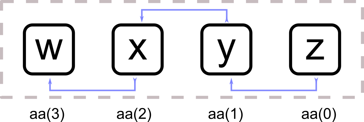
- Try this!
- What happens when you set gate 0 to
1and clock the circuit? - What happens when you set any other gate to
1and clock it? - Why?
- What happens when you set gate 0 to
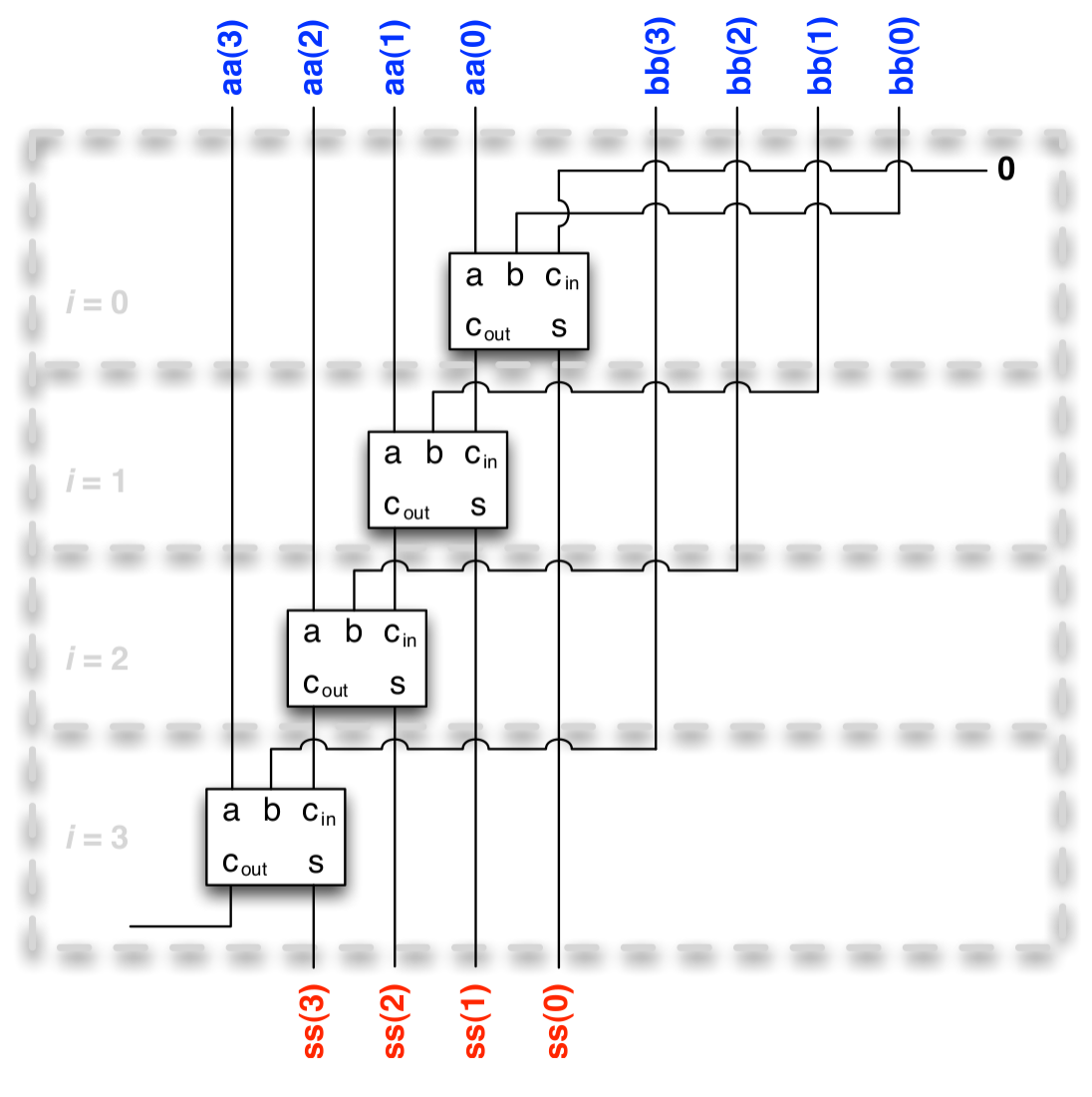
minilog example: building the incrementer
import minilog.* // Note: minilog not tinylog

def buildHalfAdder(ai: Gate, c: Gate) = (ai && c,
  (!ai && c)||(ai && !c))

def buildIncrementer(aa: Bus) =
  var c = aa.host.True   // initial carry is true
  val r = new Array[Gate](aa.length)
  for i <- 0 until aa.length do
    val (c_out,s) = buildHalfAdder(aa(i), c)
    r(i) = s
    c = c_out
  end for
  new Bus(r.toSeq)
end buildIncrementer
In combinational logic circuit without feedback this would increase the input once.
Now for the feedback:
val n    = 4
val c    = Circuit()
val ins  = c.inputs(n)
val outs = buildIncrementer(ins)
ins.buildFeedbackFrom(outs)
We can play with it using minilog Trigger:
val t = Trigger(c)
t.watch("ins",  ins.reverse)
t.watch("outs", outs.reverse)
t.go()
minilog example: building an accumulator-adder
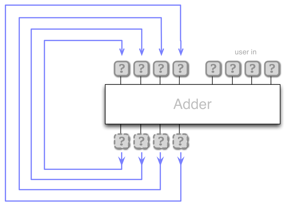
def buildAdder(aa: Bus, bb: Bus) : Bus =
  val pairs = aa.zip(bb)
  var c : Gate = aa.host.False
  // Create sequence of gates using loop
  val sum = for (a,b) <- pairs yield
    // Construct s gate for this bit
    val s = a ^^ b ^^ c       // ^^ means XOR
    // Update carry
    c = ( (a && b) || (a && c) || (b && c) )
    s // Return s gate
  new Bus(sum)
end buildAdder
val n         = 8
val c         = Circuit()
val accum_in  = c.inputs(n)
val user_in   = c.inputs(n)
val accum_out = buildAdder(accum_in, user_in)

accum_in.buildFeedbackFrom(accum_out)
val t = Trigger(c)
t.watch("accum_in",  accum_in.reverse)
t.watch("user_in",   user_in.reverse)
t.watch("accum_out", accum_out.reverse)
t.go()
Memory module (one word)
- Need to
- Keep state of a word (bus)
- Read the currently stored word
- Write a new word to the memory
- Feedback allows us to keep state
- How can we store a word?
- How can we retrieve the stored word?
We will need some more logic than a bus simply feeding back into itself.
Memory module (one word)
- When Gate read enable is 1 the Bus data out will immediately be set to the word stored in the memory
- When Gate write enable is 1 and the circuit is clocked the word in Bus data in is written to the memory


A two word memory (concept)
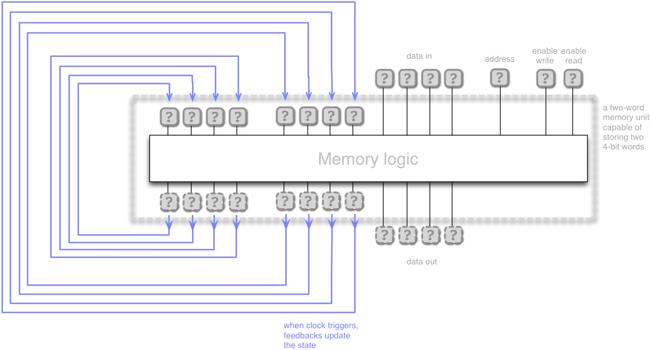
- A 'memory bank' a set of one word memory modules
- Now, we need an address to indicate which module we want to read from or write to
- Compare to a
BufferorArrayin Scala addressis an 'index' into the memory- When
enable writeis true the word indicated byaddressis overwritten bydata in - When
enable readis true the word indicated byaddressis copied todata out
Address bus width and memory size
The width of the address bus limits the size of the address space, that is how many different memory places that can be accessed. When implemented in hardware this is a physical limitation of the machine.
How many bits are needed to address a memory bank of 8 words?
(Hint: it is 1 bit for a 2 word memory.)
- Answer 3. We need to distinguish between 8 different modules using binary digits. \(\lceil\log_2 8\rceil = 3\)
- What is the maximum possible memory of a computer with 8 bit address bus and a word (data bus) size of 1 byte?
- Answer: \(1\) (byte/word) \(\times 2^{8}\) (addressable words) = \(256\) bytes
The Armlet
Let's start conceptually building a programmable processor architecture
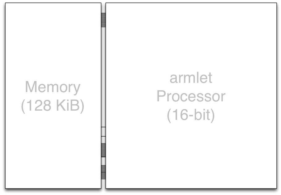
- 128 KiB memory connected to a 16-bit Processor
- 16-bit address and data buses
- Instruction set inspired by the ARM architecture
- Simplified design (no pipelining, no multithreading, only one core…)
- All using the
minilogpackage!
- This is an example of a von Neumann (a.k.a Princeton) computer architecture
- A central processing unit made up of control and arithmetic logic units on a data path,
- connected to a memory unit storing both program and data.
- Input and Output (I/O) devices read and transfer data to outside media
The Data Path
Describes how data is transformed in one clock of the Processor
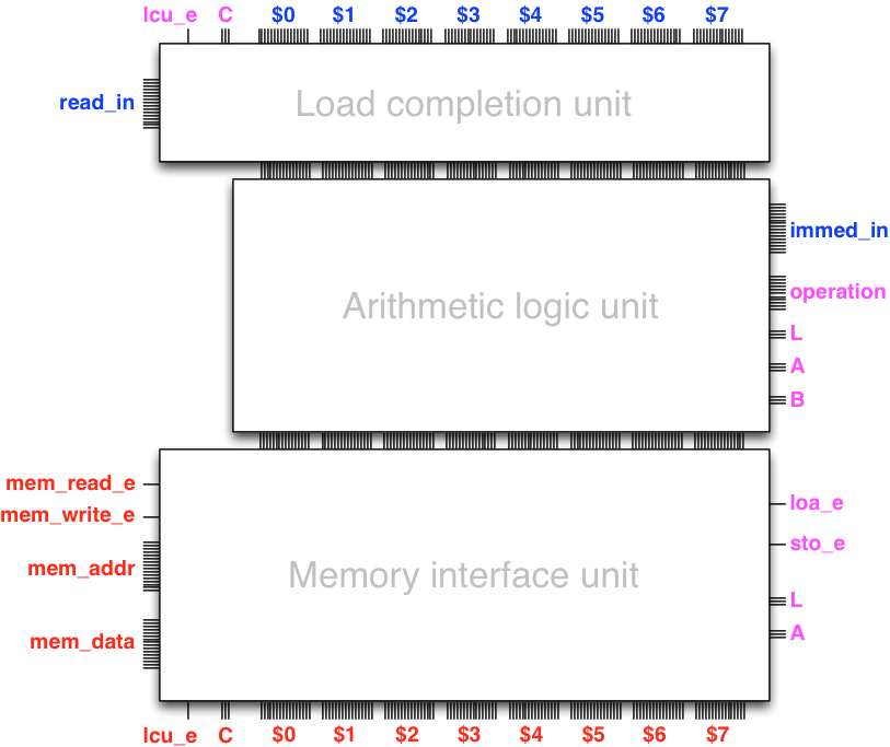
- Internal state (registers)
- Ability to load data to processor (Load completion unit)
- Ability to compute (Arithmetic logic unit)
- Ability to save result to computer memory (Memory interface unit)
Registers
- A register works like a 'variable' built in to a circuit
- We have seen examples of circuits able to keep and update their state
- The accumulator-adder, for instance, has a built in 'variable' which gets updated
- In processor architecture such variables are called registers
- Our architecture will have eight 16-bit registers:
$0,$1,$2,$3,$4,$5,$6, and$7
Arithmetic logic unit
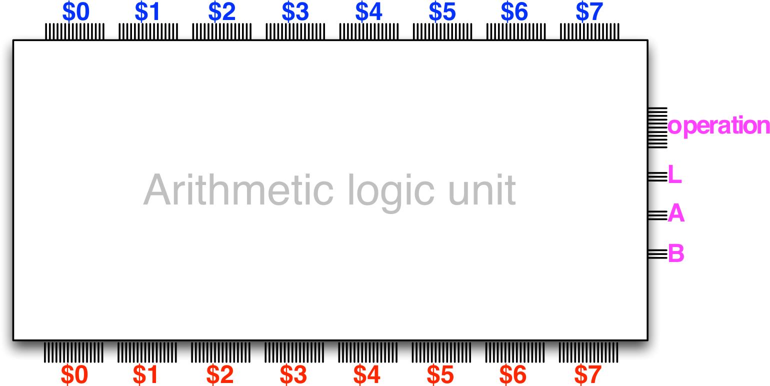
- Same principle as the accumulator-adder-subtracter design!
- Eight registers:
$0to$7 - Operations such as addition, subtraction, shift, AND, OR…
operationselects which one is used the current 'tick'
Lis the number (0-7) of the register where the result is storedAis the number (0-7) of the register of the first operandBis the number (0-7) of the register of the second operand
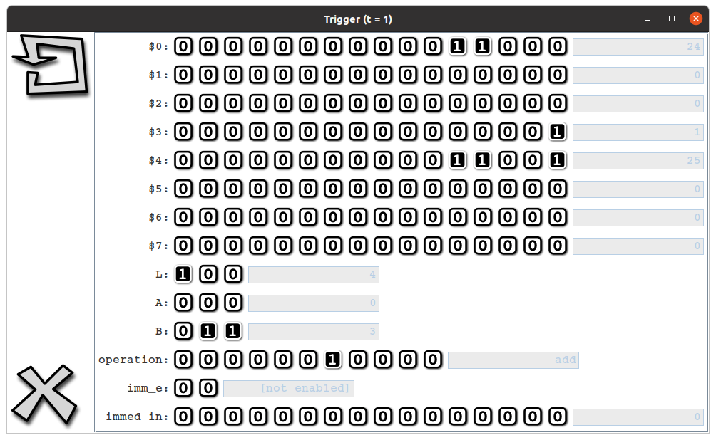
Arithmetic logic unit
Example: to have the ALU put the sum of $0 and $3 into $4
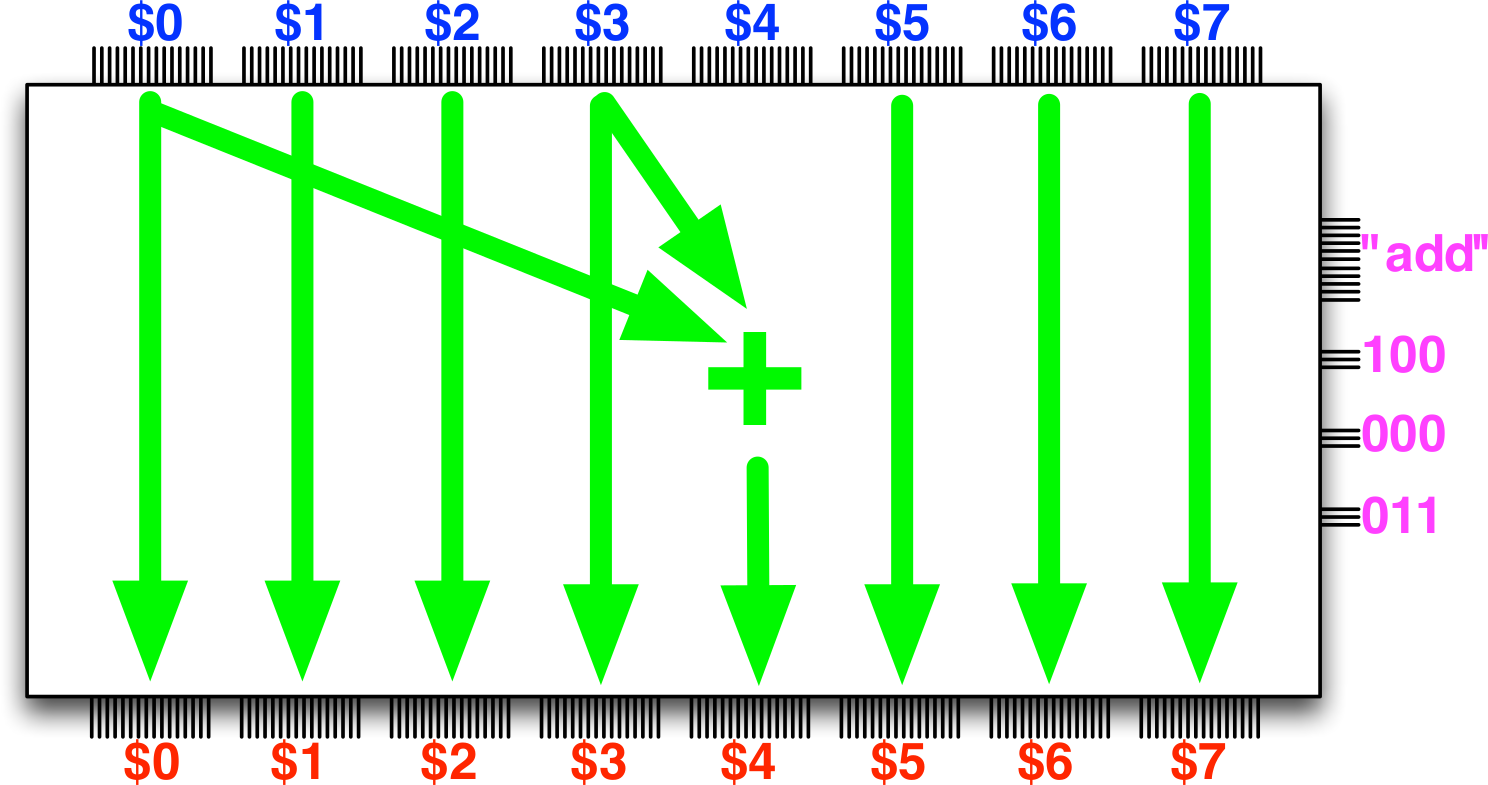
- Set
operationto the number corresponding to addition instruction - Set
Lto100(4) - Set
Ato000(0) - Set
Bto011(3) - Clock the circuit
Adding immediate data to the ALU
With a slight upgrade, the ALU can handle 'constant' in operations
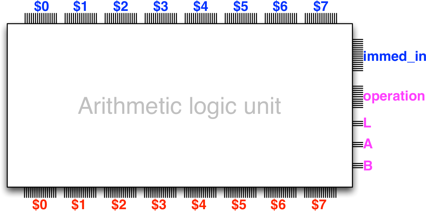
immed_inis a 16-bit word that can be used in place of a register- Handy, because we don't need to waste registers to hold constants
- Two versions of some instructions, e.g.
add:- one that adds the two registers indicated by
AandB, - another that adds the register indicated by
Ato the constant stored inimmed_in
- one that adds the two registers indicated by
Playing with the ALU
The armlet package (part of the exercises) comes with a UI that lets you test out the ALU by setting different inputs and clocking the circuit.
- You can start it by running the program
launchALUTrigger.scalain the exercise package, or - Create an ALU trigger in the console (after importing minilog)
scala> new ALUTrigger()
Storing and loading data
- Eight 16-bit registers is hardly sufficient for most processing needs
- More storage requires interfacing with external (to the processor) memory circuits
- Our processor has 16-bit words, meaning that it can address \(2^{16}\) memory locations
- Each memory location in turn contains one 16-bit word of data (2 bytes)
- That is \(2^{16} \times 2\) bytes = 128 kibibytes of data
- The Memory interface unit is responsible for issuing operations to the memory
- load from - and store to memory
- The Load completion unit, in turn, is responsible for setting a register to a value retrieved from memory at the beginning of the data path
Are we there yet?
Do we have a programmable computer?
Almost, we somehow need to load our program - the instructions for the data path - and have them executed automatically.
More on that next time.
Exercises
- Feedback quiz
- Oscillator
- Linear-feedback shift registers
- Memory
- Build a one word memory module
- Build a multi-word memory module (hints)
- Sequential multiplier
- Use a single adder over and over to do multiplication
- (Challenge problem: pipelined multiplier)
- Note:
minilogallows both^^and+for XOR, they do the same! - Hints:
- You can always get the
Circuitof aGateorBusby using the.hostmethod - You can only call
buildFeedbackFromon input elements - Memory: Note the given functions to build decoder and selectors
- Multiplier: pay attention to the description of
loadEnableandready - Remember that
Busis a sequence!
- You can always get the
- Use the given
play-programs to check the behaviour of your implementations- Note that you will need to uncomment parts of the play code for them to work!!
- (This is because they contain code to visualise different cases)
- And don't forget the last
t.go()line