The armlet processor
The data path
At this point you may want to recall the design of the
data path, and in particular the armlet instructions for operating
the data path from Round 4: Sequential logic, state and feedback.
The program counter and processor status
To upgrade our design to a full stored-program architecture, it will be convenient to have available two more registers.
The program counter (PC) is a register that stores the memory address from which the current instruction was loaded (or is currently being loaded, in case we are loading a 32-bit instruction and are still waiting for the immediate data to arrive from memory).
The processor status (PS) register contains status bits that are used to control program execution, in particular the processor status includes three bits that store the result of the most recent comparison instruction that was executed.
The comparison instructions
The full armlet architecture supports two comparison
instructions, one that takes two register operands, and one
that compares a register operand with 16 bits of immediate data:
cmp $A, $B           # compare $A (left) and $B (right)
cmp $A, I            # compare $A (left) and I (right)
The result of the comparison is stored in three flag bits in the processor status register: equal, greater, and above.
The equal flag is set to 1 if and only if the left operand equals the right operand; otherwise the flag is set to 0. The greater flag is set to 1 if and only if the left operand is greater than the right operand (both operands are viewed as signed integers); otherwise the flag is set to 0. The above flag is set to 1 if and only if the left operand is greater than the right operand (both operands are viewed as unsigned integers); otherwise the flag is set to 0.
The processor status register stores the result of the comparison until the next comparison is made, at which point the status is updated to reflect the result of the next comparison.
Default flow of execution
When instructions are loaded from memory for execution, the default is to load the next instruction from the memory address that immediately succeeds the address of the current instruction. That is, after the clock triggers, the value of the program counter is the current value of the program counter plus one.
The default flow of execution may be altered by jump instructions and branch instructions.
The jump and branch instructions
A jump instructs that the program
execution is to continue at the memory address given as an operand,
which may be either the contents of a register or an address supplied
as immediate data. For example, jmp 12345 instructs that the
next instruction must be loaded from the memory word with address 12345.
In effect, a jmp is like a mov whose target is
the program counter – the execution will continue from the
indicated address as soon as the clock triggers.
A branch instruction is like a jump, but the jump is
executed conditional to the current contents of the
program status register, that is, the result of the most recent comparison
instruction. For example, the branch instruction
beq 12345 jumps to the address 12345
if the result of the most recent comparison was
that the two operands were equal;
otherwise the processor follows the default flow of execution.
Here is a summary of all the jump and branch instructions that take a register operand:
jmp $A           # jump to address $A
beq $A           # ... if left == right (in the most recent comparison)
bne $A           # ... if left != right
bgt $A           # ... if left > right  (signed)
blt $A           # ... if left < right  (signed)
bge $A           # ... if left >= right (signed)
ble $A           # ... if left <= right (signed)
bab $A           # ... if left > right  (unsigned)
bbw $A           # ... if left < right  (unsigned)
bae $A           # ... if left >= right (unsigned)
bbe $A           # ... if left <= right (unsigned)
Here is a summary of all the jump and branch instructions that take an immediate operand:
jmp I            # jump to address I
beq I            # ... if left == right (in the most recent comparison)
bne I            # ... if left != right
bgt I            # ... if left > right  (signed)
blt I            # ... if left < right  (signed)
bge I            # ... if left >= right (signed)
ble I            # ... if left <= right (signed)
bab I            # ... if left > right  (unsigned)
bbw I            # ... if left < right  (unsigned)
bae I            # ... if left >= right (unsigned)
bbe I            # ... if left <= right (unsigned)
Jumps and branches versus if-then-else, while, and such
The jump and branch instructions may appear somewhat cumbersome, but they are sufficient to implement all the functionality offered by higher-level constructs such as an if-then-else statement or a while-loop in Scala. We will get practice on this soon.
Reset
So how does the processor logic start to execute instructions,
and from which memory address? Here our convention is to start
from the memory address 0. The processor is instructed to start
by means of a reset input. Set the reset input to true,
trigger the clock, and set the reset input back to false.
When the clock triggers, all processor registers are reset to zero, and the memory interface unit issues a read at address 0. Then it is off to the races – the processor will follow the rules of execution until there is a halt.
Halt
The processor stops the execution if it encounters and unused
instruction opcode or a halt instruction hlt.
hlt # halt execution
The processor signals that a halt has occurred by giving
true output to hlt_f. A halt may be
reversed only by issuing a processor reset.
Trap (debugging)
For debugging purposes the processor supports a trap
instruction trp that can be used to signal a break
in execution so that the programmer can inspect what
the processor is doing.
trp # trap (break out of execution for debugging)
Our Ticker interface to the armlet processor will
break the execution of a running program whenever a
trap instruction is encountered.
The armlet architecture (*)
The complete and upgraded armlet architecture is
summarized in the following diagram:
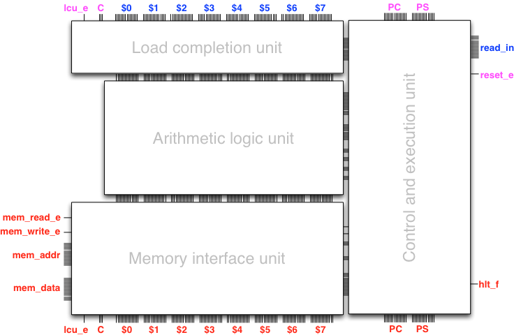
The only external inputs to the processor are the input
bus read_in that receives the result of the read
from memory, and the reset input reset_e for
issuing a processor reset.
The external outputs of the processor are the halt indicator
hlt_f and the outputs mem_read_e,
mem_write_e, mem_addr, mem_data to
control the memory unit.
The control and execution unit is responsible for loading and executing the program. The unit is partitioned internally into three subunits, each of which interacts with the units of the data path.
The instruction loader unit takes care of loading instruction from memory, in particular in the case when the instruction consists of multiple words (that is, has an immediate data word).
The instruction decoder unit decodes a complete instruction it receives from the instruction loader unit and configures the data path.
The jump and branch unit updates the value of the program counter
and the processor status register based on their current values,
the current instruction, and the result of comparing the
operands in the ALU. The jump and branch unit also configures
the memory interface unit to issue a memory read for the next
instruction, unless the current instruction is a load (loa)
or store (sto), in which case the processor must wait until
the load or store completes and only then issue the read for the
next instruction.
As can be read from the rough description above, the full armlet
architecture is already somewhat intricate because of the necessary
choreography between units to access the memory.
Yet it is all just sequential logic. In fact, the complete armlet
processor is exactly 5574 Gate-objects in minilog!
In short, sequential logic is all one needs to build a programmable computer
from scratch. In our case it took less than 500 lines of Scala code
in package armlet to build a simple processor architecture.