Introduction
State, evolving the state
After Round 3: Combinational logic we now have a fair bit of insight into combinational logic and what it can do. Yet, combinational logic appears fairly restrictive. We can design our circuits to be configurable, but this appears to be nowhere near the level of versatility that one would expect from a programmable computer. Something must be missing from the big picture.
Say, think about a simple pocket calculator (or the calculator app in your handheld device). Suppose you have a list of 100 numbers whose sum you need to compute. Using the calculator, you can add up the numbers by keying them into the calculator, one number at a time. The machine maintains the sum and evolves it as you key in the numbers.
What we appear to be missing is the ability to maintain a state, and the ability to evolve that state.
Let us consider another, even more elementary example.
Let us think about a (binary) counter device that adds one to a count every time you push a button:
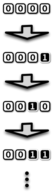
Circuit-wise we of course know how to design an incrementer circuit in combinational logic (recall Round 3: Combinational logic), so it would appear like we should be in good shape to arrive at a counter device. So how do we do it?
Feedback
If you think about it a little, to turn an incrementer into a counter it suffices to feed the output back to the input. That is, whenever the button is pushed, we set the values of the input elements to equal the the values of the outputs. The gates of the circuit will then stabilize to reflect the new values of the inputs, and we get new values of the outputs. Until we press the button again, and feedback occurs again, and so forth. The same combinational logic is used over and over again to evolve the state.
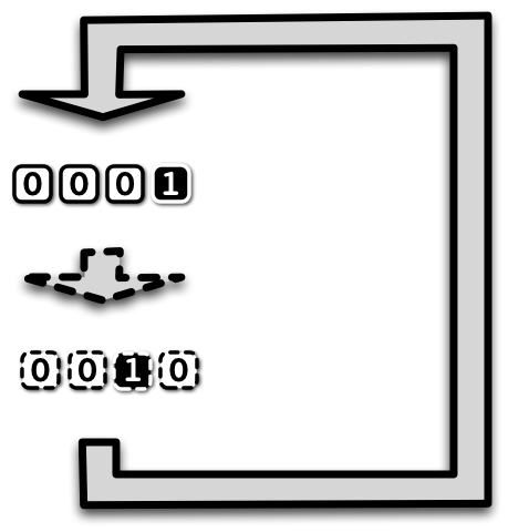
This is the gist of sequential logic. We take a combinational circuit and feed the values of some of its output gates back to some of its input elements, whenever the clock signal triggers the feedback.
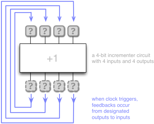
Let us review this idea with a little more detail before turning to Scala programming again. Here is a more detailed view to a counter circuit with feedbacks from the outputs of the incrementer to the inputs:
Let us now think how this circuit operates over time.
In the context of sequential logic, time is measured in clocks. That is, the time \(t=0,1,2,\ldots\) is equal to how many times the clock signal has triggered since system start. At start, \(t=0\).
Here is an illustration how the circuit operates over time:
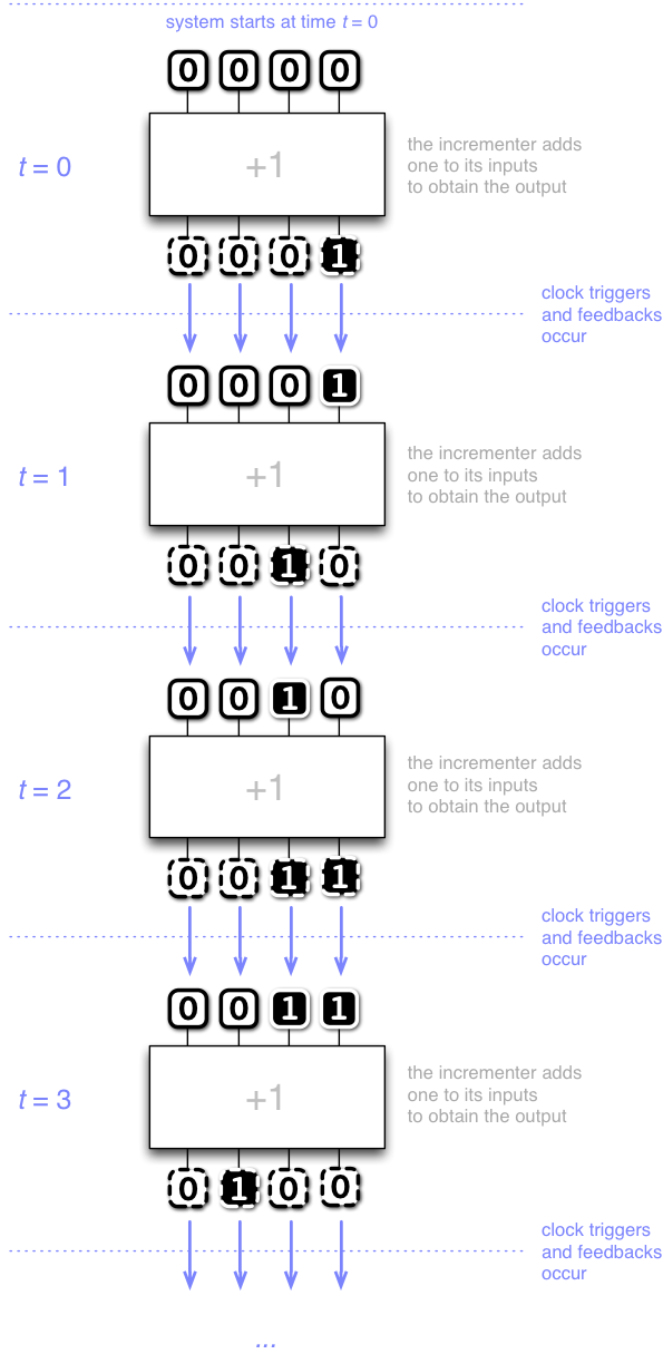
Observe that sequential logic is very simple indeed (compared with all the trouble we had to go to learn combinational logic!):
When the clock triggers, the specified feedbacks happen.
Nothing more, nothing less.
Now let us turn to Scala programming to start witnessing the power of sequential logic.
Upgrade from tinylog to minilog
Recall the tinylog package from Round 3: Combinational logic?
A wonderful feature of encapsulation is that client code remains essentially oblivious to changes-in-implementation, assuming the interfaces to that implementation (that is, the classes and their methods visible to clients) remain mostly unchanged.
Our intent in this round is to witness such a change in implementation.
Namely, we will upgrade package tinylog from Round 3: Combinational logic
to package minilog in Round 4: Sequential logic, state and feedback.
This is to (a) get a more efficient circuit simulation,
and (b) extend the package with a feedback mechanism to enable us to build
sequential logic.
From a pedagogical perspective it is of course also important to show
that such changes in the underlying implementation are possible, and enabled
by careful design of the original interfaces. A further pedagogical motivation
is that we get to introduce the principle of designing with patterns by
reviewing the designs of both tinylog and minilog.
Before we proceed with the details of the upgrade to minilog, however,
let us play with sequential logic.
Our first design with sequential logic – the counter
Ambitious goals again have humble beginnings. Let us implement the counter circuit.
We start by recalling from Round 3: Combinational logic how to build an incrementer, in combinational logic.
import minilog.* // Note: in this round we use the package minilog
                 //       instead of tinylog.

// Here is a builder for an incrementer

def buildHalfAdder(ai: Gate, c: Gate) = (ai && c, (!ai && c)||(ai && !c))

def buildIncrementer(aa: Bus) =
  var c = aa.host.True   // initial carry is true
  val r = new Array[Gate](aa.length)
  for i <- 0 until aa.length do
    val (c_out,s) = buildHalfAdder(aa(i), c)
    r(i) = s
    c = c_out
  end for
  new Bus(r.toSeq)
end buildIncrementer
Now we are ready to implement the counter circuit.
val n    = 4
val c    = new Circuit()                   // a host object for our gates (new in minilog)
val ins  = c.inputs(n)                     // have the host create a new bus of n input elements
val outs = buildIncrementer(ins)           // build an incrementer
ins.buildFeedbackFrom(outs)                    // feed the outputs back to the inputs (new in minilog)
Observe the feedback statement ins.buildFeedbackFrom(outs).
This statement simply indicates that each input element in the bus ins
is to receive its value from the corresponding output in the bus outs
when the feedback (clock) is triggered.
Recall the Toggler tool in tinylog ?
The Toggler tool has been upgraded in minilog into a tool
called Trigger, which we will put to use right now:
val t = new Trigger(c)                   // trigger requires a host object
t.watch("ins",  ins.reverse)             // we can watch gates or buses in the host object
t.watch("outs", outs.reverse)            // ... reversion shows least significant bit on the right
t.go()                                   // opens up the graphical interface
Observe the central new feature of Trigger, namely the
trigger button that triggers the clock (and feedback):

Now give a few clicks to the button, and watch the binary counter run!
Our second design – the accumulator-adder
Let us now return to the example of taking the sum of a list of integers. Say, suppose we want to evaluate (in binary) the sum of
00001011,00101010,00010101, and01010111.
How would we design a machine to help us with this task?
We know how to build an adder circuit, so building sequential logic that accumulates a sum should be within the scope of our tools. Say, we feed the output of the adder back to its first input bus. This enables us to accumulate a sum, one summand at a time, by keying each summand in via the second input bus, and triggering the clock (feedback) to accumulate the sum.
Here is a builder for an adder (written in functional style):
def buildAdder(aa: Bus, bb: Bus) =
  new Bus(
   ((aa zip bb).scanLeft((aa.host.False, aa.host.False))) {
     case ((s,c),(a,b)) => (a+b+c,(a && b)||(a && c)||(b && c))
   }.drop(1).map(_._1))
end buildAdder
So now we are ready to build the accumulator-adder:
val n         = 8
val c         = new Circuit()
val accum_in  = c.inputs(n)
val user_in   = c.inputs(n)
val accum_out = buildAdder(accum_in, user_in)

accum_in.buildFeedbackFrom(accum_out)
Let us witness this in Trigger:
val t = new Trigger(c)
t.watch("accum_in",  accum_in.reverse)
t.watch("user_in",   user_in.reverse)
t.watch("accum_out", accum_out.reverse)
t.go()
Now, toggle “user_in” to whatever value you want, and trigger feedback
to have it added to the accumulator!
The feedback from accum_out to accum_in now in effect acts
as \(n = 8\) bits of memory, which is used to store and accumulate the sum.
The accumulator-adder can in fact be viewed as an extremely simple special-purpose processor design.
The processor has only one operation it can perform, namely add the contents of an 8-bit user input into an 8-bit register (or, the accumulator).
Our third design – the accumulator-adder-subtracter
Our third design already includes configurable functionality. Namely, the machine can either add or subtract the user input from the accumulator, depending on what the user selects.
Here is a builder for a subtracter:
def buildSubtracter(aa: Bus, bb: Bus) =
  new Bus(
   ((aa zip bb).scanLeft((aa.host.False, aa.host.True))) {
     case ((s,c),(a,b)) => (!(a+b+c),(a && !b)||(a && c)||(!b && c))
   }.drop(1).map(_._1))
end buildSubtracter
So now we can build the accumulator-adder-subtracter:
val n         = 8
val c         = new Circuit()
val accum_in  = c.inputs(n)
val user_in   = c.inputs(n)
val sel       = c.input()
val res_add   = buildAdder(accum_in, user_in)
val res_sub   = buildSubtracter(accum_in, user_in)
val accum_out = (res_add && !sel) | (res_sub && sel)

accum_in.buildFeedbackFrom(accum_out)
Let us witness this in Trigger:
val t = new Trigger(c)
t.watch("accum_in",  accum_in.reverse)
t.watch("sel",       sel)
t.watch("user_in",   user_in.reverse)
t.watch("accum_out", accum_out.reverse)
t.go()
After a little bit of play, let us now pause and reflect. Sequential logic has suddenly made our tools more powerful. We can now maintain a state inside a circuit, and evolve it according to combinational logic that can be configured (for example, either to add or to subtract) by toggling input.
Towards understanding the computer
Let us think about our quest to understand the computer. It appears we have come a fair way now, but yet the notion of programmability (e.g. a console that executes our commands) appears more powerful than configurability. For example, we can now add integers by keying them into input elements of sequential logic and then triggering the clock.
But how do we instruct the machine to, say, take the sum of the first 100 million positive integers and then report back to us? It still appears that we do not have the full picture. Yet we are not far from our goal.
Building an instructable data path – a roadmap for this round
Our objective in this round is to familiarize ourselves with sequential logic and continue towards our objective of understanding the computer. In fact, during this round we will cover most of the way to a fully functional, programmable processor architecture.
Yet again our strategy is to proceed from the bottom up. We start by upgrading our circuit-building and -simulation tools to sequential logic. In the process we will introduce the principle of designing with patterns to structure our programs in Sequential logic in Scala (*)
Once we have package minilog ready, we have all the tools
required to fully and finally resolve the mystery of the
programmable computer. In essence, it is all just sequential logic.
To back this claim, our goal in the next two rounds is
to deploy sequential logic to build the armlet, in many respects
a substantially simplified but yet fully programmable processor
architecture loosely inspired by the ARM architecture.
Note
Most modern mobile devices and embedded systems have long used processors based on the ARM architecture. In fact, it is likely that you currently have an ARM processor running in your pocket or purse.
In recent years even personal computers based on the ARM architecture have become more common. For example, in 2020 Apple introduced products in their Air Pro, and Mini lines built around their M1 system.
Our objective in this round to build the data path of the armlet.
That is, the part of the processor that maintains and manipulates
the data in our computations, one step (clock tick) at a time.
The two key components of the data path are the arithmetic logic unit
(that implements the arithmetic and logic operations in our computations)
and the memory interface unit (that loads and stores words of data
from a memory unit outside the processor). The armlet data path
Furthermore, our goal is to be able to instruct the data path. That is, we want our design to be such that we can configure what the data path does at any given step by means of an instruction, that is, one word of control input to combinational logic. The armlet instruction set
Yet again what is above may sound like a formidable objective, but
in fact we have essentially all the tools ready. The armlet
data path is in essence nothing but a somewhat more intricate
accumulator-adder (recall our design above): a combinational logic
circuit with simple feedbacks from selected outputs to inputs.
In the exercises we will practice sequential logic design ranging from simple oscillators to the design of a pipelined multiplier unit.
In the next round, we extend the single-step functionality of the data path with an execution-and-control unit to obtain a fully programmable Von Neumann architecture, which we then proceed to program. Finally, we take a look at Scala itself and the progression from a Scala program to execution on actual physical hardware.