Introduction
Building machines that compute with bits, from the bottom up
In Round 2: Bits and data we observed that computers represent information as a sequence of bits with an agreed format.
Our intent in this round is to understand how to design and build machines that carry out simple operations with bits. In subsequent rounds we will build on top of this understanding to eventually arrive at a programmable computer, but for now we will be content on a somewhat more modest goal.
This strategy of starting small and gradually building our way up towards large and more ambitious designs is called bottom-up design.
Characteristic to bottom-up design is that we build up both the design and our tools (that is, Scala programs) to work with the design simultaneously as our understanding of the problem increases.
Characteristic to bottom-up design is also that we systematically test (play with) our designs at every stage of the process. This is important because we want
to get a hands-on understanding of what is going on, and
to catch bad aspects of the design (such as errors or poor usability) as early as possible.
Besides learning some of the central principles how to design machines that compute with bits, our intent is to build up our expertise and experience as programmers. One great aspect about programming is that we can build our own tools as we build up a design. And the better tools we have, the more time we can devote to studying and having fun with the design. Increased programming convenience means increased productivity.
To set up a goal for this round, let us build (more precisely, simulate using Scala) from first principles a machine that adds two 64-bit integers.
Logic gates
To arrive at our goal, clearly we must have some means of manipulating individual bits. Disregarding the details of an actual physical implementation in terms of wires, transistors and such, the most elementary components for manipulating individual bits in hardware design are called logic gates.
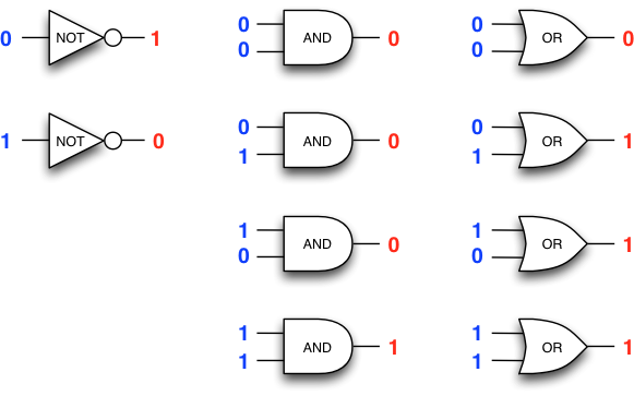
The most common logic gates are NOT, AND, and OR, each of which
evaluates the corresponding Boolean function of the Boolean values
(true/1 or false/0) – received as inputs.
The value of a gate is the value of
the Boolean function on the received input values. The value of
a gate is frequently alternatively called the
output of the gate.
Before proceeding further, let us pause and reflect that logic gates are simple devices indeed, and it is not a great stretch of imagination that such simple devices can be operated extremely fast and built in extremely small scale.
The power of combination
What makes logic gates powerful is that they can be combined so that the value (output) of one gate propagates to the inputs of one or more other gates, and so forth, yielding combinational logic. The result of combining one or more logic gates is called a logic circuit or Boolean circuit.

The Boolean circuit above tests whether its two inputs are
identical (that is, the circuit has the value true
if both its inputs have the same value),
which we can witness by evaluating the circuit with
all possible \(2\times 2=4\) combinations of the two input values.
Each evaluation propagates values through the circuit from the inputs to the output:
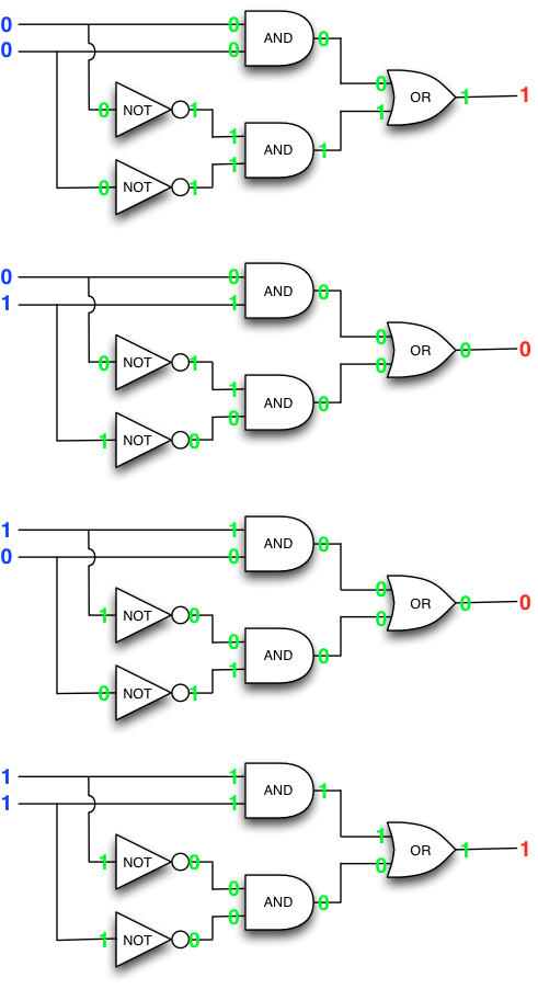
Reviewing the four evaluations above, we see that the circuit tests its inputs for equality exactly as was hoped for.
We now have all the basic building blocks to start building rather formidable machines from humble beginnings, while learning the art of programming in the process.
Building combinational logic in Scala
Let us now turn to Scala programming and write a tiny Scala package to build combinational logic, one gate at a time.
Here our intent is to build up our tools as we go, following the principle of bottom-up design. Accordingly, we start with a minimalist package that we will then shape further as our understanding increases. You can do the next few steps in the console, or in your own package file.
Let us start with an abstract base class Gate:
abstract class Gate():
  def value: Boolean     // implemented by the extending classes
end Gate
The base class is extended by concrete classes InputElement,
NotGate, AndGate, and OrGate
that implement the concrete functionality.
The class InputElement implements an input element that
maintains its value that can be set with the method
set(v: Boolean). In essence, input elements are our
interface for feeding bits of data into the circuit.
class InputElement() extends Gate():
  var v = false                         // default value is false
  def set(s: Boolean) = { v = s }
  def value = v
end InputElement
The logic gates implement only the method
value: Boolean, which uses recursion to
determine the actual value based on the value(s) of the input(s).
class NotGate(in: Gate) extends Gate():
  def value = !in.value
end NotGate

class OrGate(in1: Gate, in2: Gate) extends Gate():
  def value = in1.value || in2.value
end OrGate

class AndGate(in1: Gate, in2: Gate) extends Gate():
  def value = in1.value && in2.value
end AndGate
Finally, when building circuits it is convenient to have available gates that have a fixed value.
class ConstantGate(v: Boolean) extends Gate():
  def value = v
end ConstantGate
Of course in practice we really need only two constant gates, one that
always has value true and one that always has value false,
so we can just as well build these only once and leave them
in a companion object to class Gate.
object Gate:
  val False = new ConstantGate(false)
  val True  = new ConstantGate(true)
end Gate
Our tools for building combinational logic are now ready. We can depict our design using the following class diagram:
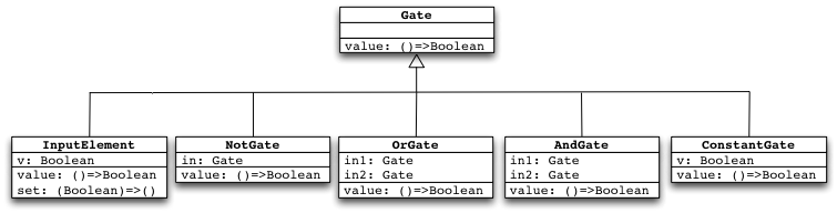
In principle, this is all we need to build all the combinational logic we want. (In practice, we will be improving the package somewhat as we go, to get increased convenience.)
To get started, let us build our previous example circuit, which is redisplayed below for convenience. Note that for illustration we have named the gates with the identifiers used in the Scala code that builds the circuit.
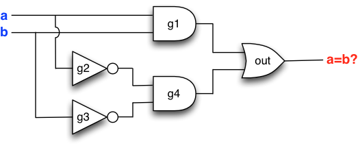
Here we go, one gate at a time (compare with the figure above):
// Build a simple circuit

val a = new InputElement()
val b = new InputElement()
val g1 = new AndGate(a,b)
val g2 = new NotGate(a)
val g3 = new NotGate(b)
val g4 = new AndGate(g2,g3)
val out = new OrGate(g1,g4)
Before reflecting what the code actually does, let us first test the circuit at the console. To do this yourself, copy and paste the Scala code above to the console. Assuming you have done this, we can set values to the input elements and see what the output evaluates to (do this yourself at the console!). Here is one example:
scala> a.set(false); b.set(false)
scala> out.value
res: Boolean = true
Looks good if we compare with the manual evaluation depicted earlier. But let us test the remaining input combinations just to be safe:
scala> a.set(false); b.set(true)
scala> out.value
res: Boolean = false
scala> a.set(true); b.set(false)
scala> out.value
res: Boolean = false
scala> a.set(true); b.set(true)
scala> out.value
res: Boolean = true
Still looks good, so our Scala-venture into combinational logic appears to be an initial success. We can build circuits and then play with them at the console (and soon, with a graphical interface) just as if we had a real physical circuit available.
Remark. Observe that the code above indeed is about as minimal as possible. The objects instantiated from the gate classes capture how the gates are connected to each other (that is, which gate supplies input to which gate), and enable us to compute the value of each gate, but nothing more.
Remark. The classes above is the basis for gates in the tinylog package, included this week’s exercise code bundle. We will be working more with it in the following sections.
Remark. In case you want a quick refresher on what objects are created
and how these reference each other when a tinylog circuit is constructed you can
consult the refresher
at the end of this chapter. (But we encourage you to first engage in a bit of
play, as per further below, and only then take the refresher.)
Playing with a circuit
All work and no play does not lead to good engineering. If we are to design circuits, we should have the tools to have a hands-on interface to play with a circuit and see the circuit in operation.
This is why we have Toggler, a simple graphical interface
built into package tinylog that enables us to manually toggle
inputs and witness what happens.
Open a console in the tinylog code project and past the following:
import tinylog.*

// Build a simple circuit

val a = new InputElement()
val b = new InputElement()
val g1 = new AndGate(a,b)
val g2 = new NotGate(a)
val g3 = new NotGate(b)
val g4 = new AndGate(g2,g3)
val out = new OrGate(g1,g4)

// Interface the circuit to Toggler

val t = new Toggler()
t.watch("a"  , a)
t.watch("b"  , b)
t.watch("g1" , g1)
t.watch("g2" , g2)
t.watch("g3" , g3)
t.watch("g4" , g4)
t.watch("out", out)
t.go()
A graphical interface to the circuit should pop up:
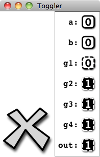
Toggle the values of the input elements by clicking on the bits


and witness the logic gates (with dashed outline)


in operation. The big “X” will close the interface.
You may configure Toggler to display the circuit as
you like, leaving out some gates or including gates that you
want to inspect.
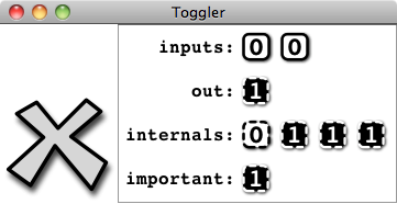
In many cases it is convenient to group gates together to sequences that are displayed consecutively:
val t = new Toggler()
t.watch("inputs",    Vector(a,b))
t.watch("out",       out)
t.watch("internals", Vector(g1,g2,g3,g4))
t.watch("important", g2)
t.go()
The previous code will result in the following view of the circuit:
Remark. Recall that one central aspect of the principle of bottom-up design
is to evolve our tools together with our understanding of the problem.
While we may view Toggler as only an amusing graphical interface to play
with a circuit, Toggler may also be viewed as part of our
programming toolkit to test and debug our circuit designs.
Remark. In case you are interested in how Toggler itself is built,
the source code of Toggler is included in the source code of
package tinylog. Be warned though, Toggler is not a particularly
clean or elegant design.
The art of bottom-up design – a roadmap for this round
Our objective in this round is to provide an example of how a bottom-up design develops with our understanding and our needs as we proceed towards our goal in small steps.
As such we should recognize the two entangled storylines involving our application (combinational logic) and our quest to become more adept at programming (bottom-up design, analysing and improving our tools, encapsulation). Such an entangled development is typical in essentially any programming project.
We start with gate-level designs, or circuits that are built at the level of individual gates in Gate-level design
Next we upgrade our tools to work with bus-level designs, or circuits that are built at the level of buses that carry words of data in Bus-level design
With sufficient background in gate- and bus-level design, we proceed to meet our goal for this round, namely circuits that implement Arithmetic with words
Our work in this round will form the basis for Round 4: Sequential logic, state and feedback.