The armlet instruction set
An instruction – a symbol in the alphabet of the machine
To be able to eventually program the armlet architecture,
we need a language that we can use to instruct the processor what to do.
For example, to configure the data path, one possibility is to specify
values to all the control inputs of the data path individually, but this
requires many bits of input, many of which are redundant. For example,
if we are setting up an arithmetic operation with register inputs only,
both the memory interface unit and the immediate data bus will be inactive.
Similarly, the arithmetic logic unit will be inactive if we are setting up
a memory load or store.
A common unit of measure in terms of the number of bits used to
configure a circuit is the word length. The armlet design
is simple enough so that 16 bits (the word length) easily suffice to
give a unique binary encoding to each operation in the set of all
possible operations in the design, except of course those operations
that take an immediate data input, which in itself takes 16 bits of data.
Such a binary word that configures the processor is called an
instruction.
From a human perspective it is also convenient to have an equivalent symbolic representation to the binary representation. For example,
add $4, $0, $3
is more human-friendly than the binary word
0011000100000110,
even if it is actually the binary word that configures the processor. The set of all available operations and their binary representations is called the instruction set of the architecture.
Binary representation of the armlet instructions (**)
The armlet architecture has two types of instructions.
The first type does not take an immediate data operand.
All these instructions are encoded in binary as one word (16 bits).
The second type includes an immediate data operand. All such
instructions are encoded in binary as two consecutive words
(16 + 16 = 32 bits), one word to set up the operation, and
one word for the immediate data.
The possible operations that we have discussed until now in fact
constitute the almost complete instruction set for the armlet
architecture. The only instructions that are yet missing are the control
and branch instructions, which we will review in
Round 5: A programmable computer.
The armlet instructions are encoded in binary using a bit-packed
format based on a 6-bit opcode (stored in the least significant bits)
that determines the meaning of the remaining 10 bits.
Here is the complete description of the armlet instruction
set, as specified in package armlet:
//
// PROCESSOR INSTRUCTION SET DESCRIPTION
//
// Each instruction is 16 bits in length (possibly followed by 16 bits
// of immediate data), and consists of an opcode and additional information.
// The least significant 6 bits of an instruction specify the 6-bit
// instruction opcode P, followed by additional information depending on
// the layout of the instruction:
//
// 1111110000000000
// 5432109876543210  (bit index)
//
// ????AAALLLPPPPPP  LA:   monadic operator                $L = op $A
// ?BBBAAALLLPPPPPP  LAB:  dyadic operator                 $L = $A op $B
// ???????LLLPPPPPP  LI:   monadic operator with imm data  $L = op I
// ????AAALLLPPPPPP  LAI:  dyadic operator with imm data   $L = $A op I
//
// ??????????PPPPPP  N:    niladic control                 op
// ????AAA???PPPPPP  A:    monadic control                 op $A
// ?BBBAAA???PPPPPP  AB:   dyadic control                  $A op $B
// ??????????PPPPPP  I:    monadic control with imm data   op I
// ????AAA???PPPPPP  AI:   dyadic control with imm data    $A op I
//
// Here:
//
// P = 6-bit opcode (0,1,...,63)
// L = lval (3-bit register identifier)
// A = first rval (3-bit register identifier)
// B = second rval (3-bit register identifier)
// ? = [unused]
//
// The opcodes, their operand types, and operand layouts are as follows:
//
val opcodes = immutable.ArraySeq(

    // Instructions that take register operands (if any)

    (0,  "nop" , "N"   , "N"   ), // no operation
    (1,  "mov" , "RR"  , "LA"  ), // rval to lval
    (2,  "and" , "RRR" , "LAB" ), // bitwise AND of rvals to lval
    (3,  "ior" , "RRR" , "LAB" ), // bitwise IOR of rvals to lval
    (4,  "eor" , "RRR" , "LAB" ), // bitwise EOR of rvals to lval
    (5,  "not" , "RR"  , "LA"  ), // bitwise NOT of rval to lval
    (6,  "add" , "RRR" , "LAB" ), // sum of rvals to lval
    (7,  "sub" , "RRR" , "LAB" ), // difference of rvals to lval
    (8,  "neg" , "RR"  , "LA"  ), // negation of rval to lval
    (9,  "lsl" , "RRR" , "LAB" ), // left logical shift of $A by $B
    (10, "lsr" , "RRR" , "LAB" ), // right logical shift of $A by $B
    (11, "asr" , "RRR" , "LAB" ), // right arithmetic shift of $A by $B
    (12, "loa" , "RR"  , "LA"  ), // load from memory word pointed by rval
    (13, "sto" , "RR"  , "LA"  ), // store to memory word pointed by lval
    (14, "cmp" , "RR"  , "AB"  ), // compare vals, result to status
    (15, "jmp" , "R"   , "A"   ), // jump to rval
    (16, "beq" , "R"   , "A"   ), // ... if status is equal
    (17, "bne" , "R"   , "A"   ), // ... if status is not equal
    (18, "bgt" , "R"   , "A"   ), // ... if status is greater than
    (19, "blt" , "R"   , "A"   ), // ... if status is lesser than
    (20, "bge" , "R"   , "A"   ), // ... if status is greater than or equal
    (21, "ble" , "R"   , "A"   ), // ... if status is lesser than or equal
    (22, "bab" , "R"   , "A"   ), // ... if status is above
    (23, "bbw" , "R"   , "A"   ), // ... if status is below
    (24, "bae" , "R"   , "A"   ), // ... if status is above or equal
    (25, "bbe" , "R"   , "A"   ), // ... if status is below or equal

    // Instructions that take immediate data

    (26, "mov" , "RI"  , "LI"  ), // rval to lval
    (27, "and" , "RRI" , "LAI" ), // bitwise AND of rvals to lval
    (28, "ior" , "RRI" , "LAI" ), // bitwise IOR of rvals to lval
    (29, "eor" , "RRI" , "LAI" ), // bitwise EOR of rvals to lval
    (30, "add" , "RRI" , "LAI" ), // sum of rvals to lval
    (31, "sub" , "RRI" , "LAI" ), // difference of rvals to lval
    (32, "lsl" , "RRI" , "LAI" ), // left logical shift of $A by I
    (33, "lsr" , "RRI" , "LAI" ), // right logical shift of $A by I
    (34, "asr" , "RRI" , "LAI" ), // right arithmetic shift of $A by $B
    (35, "cmp" , "RI"  , "AI"  ), // compare rvals, result to status
    (36, "jmp" , "I"   , "I"   ), // jump to rval
    (37, "beq" , "I"   , "I"   ), // ... if status is equal
    (38, "bne" , "I"   , "I"   ), // ... if status is not equal
    (39, "bgt" , "I"   , "I"   ), // ... if status is greater than
    (40, "blt" , "I"   , "I"   ), // ... if status is lesser than
    (41, "bge" , "I"   , "I"   ), // ... if status is greater than or equal
    (42, "ble" , "I"   , "I"   ), // ... if status is lesser than or equal
    (43, "bab" , "I"   , "I"   ), // ... if status is above
    (44, "bbw" , "I"   , "I"   ), // ... if status is below
    (45, "bae" , "I"   , "I"   ), // ... if status is above or equal
    (46, "bbe" , "I"   , "I"   ), // ... if status is below or equal

    // Unused opcodes and the processor halt

    (47, "hlt" , "N"   , "N"   ), // [unused opcode -- will halt processor]
    (48, "hlt" , "N"   , "N"   ), // [unused opcode -- will halt processor]
    (49, "hlt" , "N"   , "N"   ), // [unused opcode -- will halt processor]
    (50, "hlt" , "N"   , "N"   ), // [unused opcode -- will halt processor]
    (51, "hlt" , "N"   , "N"   ), // [unused opcode -- will halt processor]
    (52, "hlt" , "N"   , "N"   ), // [unused opcode -- will halt processor]
    (53, "hlt" , "N"   , "N"   ), // [unused opcode -- will halt processor]
    (54, "hlt" , "N"   , "N"   ), // [unused opcode -- will halt processor]
    (55, "hlt" , "N"   , "N"   ), // [unused opcode -- will halt processor]
    (56, "hlt" , "N"   , "N"   ), // [unused opcode -- will halt processor]
    (57, "hlt" , "N"   , "N"   ), // [unused opcode -- will halt processor]
    (58, "hlt" , "N"   , "N"   ), // [unused opcode -- will halt processor]
    (59, "hlt" , "N"   , "N"   ), // [unused opcode -- will halt processor]
    (60, "hlt" , "N"   , "N"   ), // [unused opcode -- will halt processor]
    (61, "hlt" , "N"   , "N"   ), // [unused opcode -- will halt processor]
    (62, "trp" , "N"   , "N"   ), // processor trap
    (63, "hlt" , "N"   , "N"   )) // processor halt
Example 1. Using the description above, let us figure out the binary representation of the instruction
sub $2, $0, $1
This is an instruction that takes two register operands (rvalues),
$0 and $1, and stores the result in a register (lvalue) $2.
Thus, the operand type is RRR (three registers) and the binary operand
layout is LAB (dyadic operator layout, register lvalue and two register
rvalues). Looking at the table of opcodes above, the opcode for a sub with
these operands is 7. We thus conclude that the word
0001000010000111
is the binary representation of “sub $2, $0, $1”.
Example 2. Using the description above, let us figure out the binary representation of the instruction
ior $7, $1, 12345
This is an instruction that takes one register operand ($1) and one
immediate operand (the decimal number 12345), and stores the result in
a register $7.
Thus, the operand type is RRI (two registers and an immediate operand)
and the binary operand layout is LAI (dyadic operator layout,
register lvalue, one register rvalue, one immediate rvalue). Looking at
the table of opcodes above, the opcode for an ior with
these operands is 28. We thus conclude that the two words
0000001111011100and0011000000111001
are the binary representation of “ior $7, $1, 12345”. The first
word configures the operation and the second word contains the immediate
data (12345 in binary).
Example 3. Let us figure out the meaning of the binary instruction
0110101111001010.
The least significant 6 bits are 001010, that is, the opcode is 10
(in decimal).
Looking at the table of opcodes above, this opcode has operand type
RRR and the binary operand layout is LAB. Based on the layout,
the next least significant 3 bits, 111, indicate that $L is $7.
The next least significant 3 bits, 101, indicate that $A
is $5. Finally, the next least significant 3 bits, 110 indicate
that $B is $6. The most significant bit is unused.
Thus, the instruction that we are looking at is
lsr $7, $5, $6
After these examples we are happy to leave the task of mapping between
binary and human-readable representations of armlet instructions
to Scala code in package armlet.
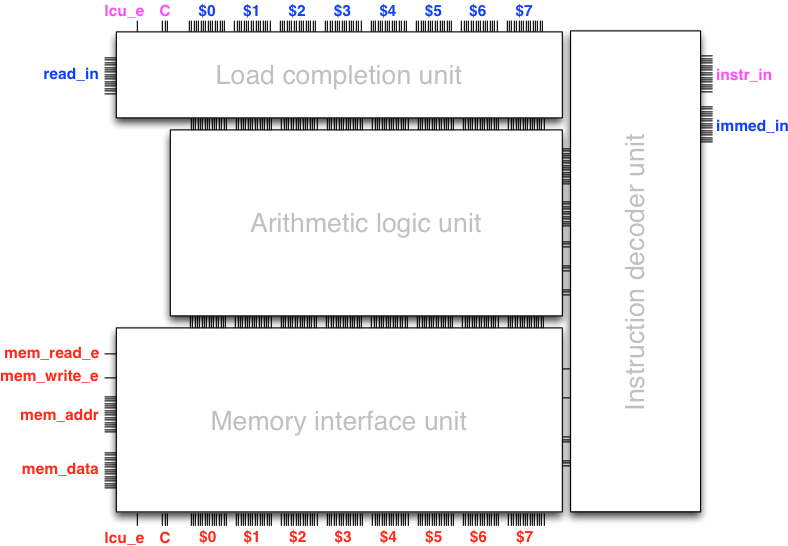
The instruction decoder unit
Let us now return to completing the design of the data path. In terms of combinational logic, we need to augment the data path with a unit that configures the data path based on the instruction given as control input (including possibly the immediate data). This functionality is implemented in the instruction decoder unit that takes as input the instruction and the immediate data (if any), and gives as output the control input to the subunits of the data path.
Instructing the data path with Trigger
We are now ready for our second Trigger session, which this
time includes the armlet data path and the instruction decoder
unit.
To play with the data path circuit compile and run the file launchDataPathTrigger.scala in the armlet source code, or copy and paste the following to an armlet-aware console:
import armlet._
new DataPathTrigger()
An interface should pop up:
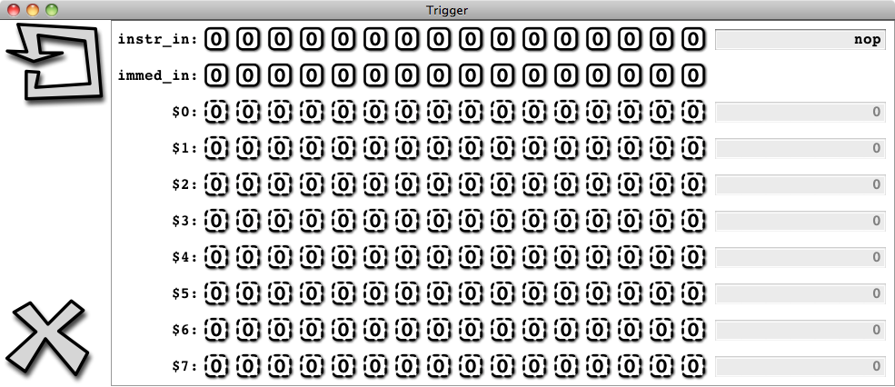
Observe that the bits of the registers do not accept toggling any more.
Our interface to the architecture is now only through the instruction
input, which we can present either in the actual binary encoding by
toggling the input bits, or in symbolic form through the text field
(which Trigger is then kind enough to translate automatically
into binary for us, assuming of course that a valid symbolic
instruction was entered!).
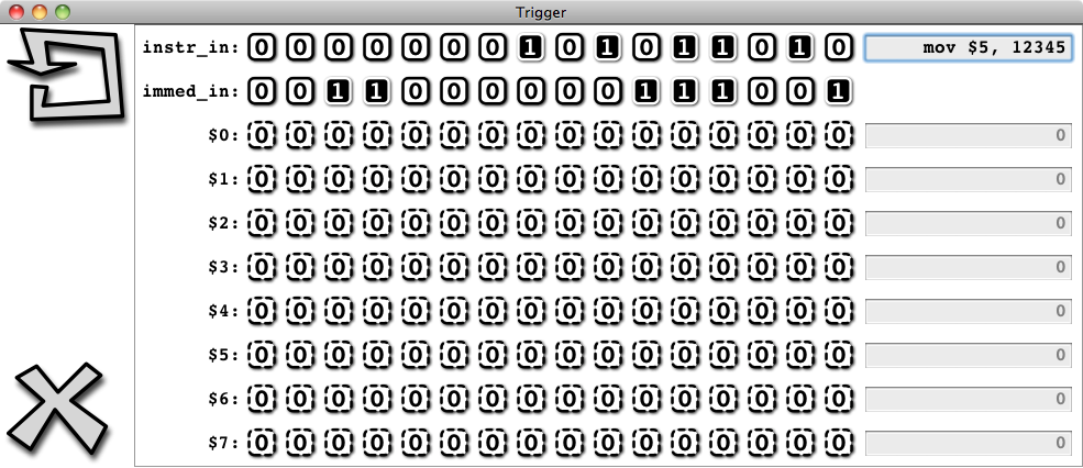
So let us push our luck, and key in the instruction “mov $5, 12345”
into the text field, taking care to press Enter to have the instruction
encoded into binary for us by Trigger:
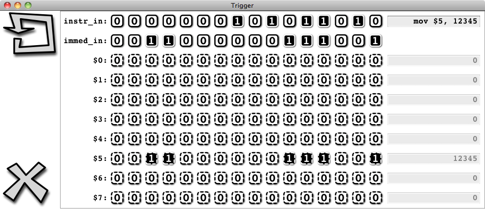
Now trigger the clock:

We observe that 12345 appears in $5 exactly as instructed:
You can now instruct the data path as you like. Just key in the instruction and witness it get executed when you trigger the clock. Alternatively, you can key in the instruction and press Shift+Enter, which both encodes the instruction (assuming it is a valid instruction) and triggers the clock. Type in a sequence of instructions and witness sequential logic in operation!
Say, suppose we want to figure out what is \(123+456+789\). The data path will do this for you, just type in the three instructions:
mov $0, 123
add $0, $0, 456
add $0, $0, 789
Or what is the same, in binary:
0000000000011010 0000000001111011
0000000000011110 0000000111001000
0000000000011110 0000001100010101
Of course this is nothing to write home about yet in terms of
programmability, since we have to type (or toggle!) the instructions
in, one by one, at the Trigger console.
Yet we have now in place all the details how this all takes place
in binary, in gate-level sequential logic. That is, we have
built from first principles a machine that we can instruct to execute
individual operations.
Towards programmability
We now know how to maintain state and how to evolve it using sequential logic. We are now very close to a fully programmable computer architecture and hence close to completing our quest for Module I: The mystery of the computer. The only aspects of a fully programmable architecture that are missing are
storing the program (a sequence of instructions) in memory, and
automating the execution of the program with sequential logic, including extending the instruction set with instructions that control this execution.
We will complete these missing pieces in Round 5: A programmable computer.